
 Programmable
Arbitrary Timing Pulse Generator
Programmable
Arbitrary Timing Pulse Generator
by Madilena Mendiola
Supervisor: Dr. Brett DePaola
Kansas State
University Physics Department REU Program
This program is funded
by the National Science Foundation through grant number PHY-1157044. Any opinions, findings, and conclusions or
recommendations expressed in this material are those of the author(s) and do
not necessarily reflect the views of the National Science Foundation.
Welcome! This page summarizes my research for the Summer of 2014 in the MOTRIMS lab of Dr. Brett DePaola at Kansas State University.
Project Overview: We have developed a multi-channel, user programmable
timing pulse generator of arbitrary TTL timing signals. Our device allows the user to specify signal outputs
on up to 10 different channels during selected time intervals using a graphical
user interface (GUI) and a BeagleBone Black (BBB)
computer. With this pulse generator we
can control the timing of multiple lasers, shutters, and other components in our
experimental setups.
Goals and Need for Device:
·
Need a simple and affordable device
that outputs timing signals on multiple channels
·
Turn devices (for example, lasers)
off/on
·
Provide timing information to data
acquisition system
·
Need a visually intuitive user
interface
·
Use a BeagleBone
Black computer
Device Features:
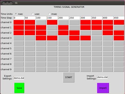
The GUI
Our
graphical user interface (GUI) specifies arbitrary TTL time pulses to be
outputted by the BeagleBone Black (BBB)
computer. The time steps can be changed
to allow unlimited temporal range. The
GUI has a matrix of buttons, and each button correlates to the signal output
for a given time interval and channel number.
Therefore, each column of buttons is correlated to a user-specified time
interval, and each row of buttons is correlated to the computer channel that
outputs the signal. Pushing a button
attributes a binary value to that button.
Our program looks at each time interval (column) of pushed buttons and
represents that collection of buttons with a single numerical value. Each column heading (time) and column value
(aggregate buttons’ status) uniquely defines the logic level for all channels
at that time step. These settings can be
saved and retrieved, and this information is then processed and outputted by
the BBB and sent to our experiment.
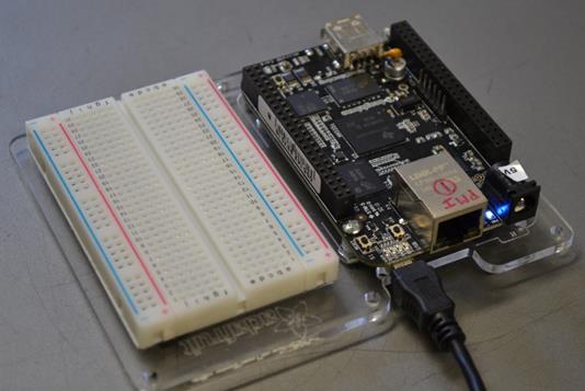
The BBB
The BBB
is attached to the data acquisition computer’s USB port. The data acquisition computer becomes the
user interface to the BBB.
The BBB
is a computer with an ARM processor and two PRUs. It operates in Linux, a flexible operating
system, and the flavor of Linux we used in this project is Ubuntu.
There
are a large number of general purpose Input and Output ports. We have 10 output channels because one PRU of
the BBB has 8 physical output pins and the other has 2 pins.
The
BBB’s output signal is based on 3.3 V TTL logic. Therefore, level shifters are used to convert
the outputs to 5 V TTL logic which is more convenient for laboratory
use.
The
minimum width you can have is the time delay of one inverter. In order to generate multiple pulses in quick
succession, we would have to utilize two channels and connect them with an AND
logic gate after a series of inverters.
Why did we want to use a BBB?
Unlike
the National Instruments device which we had used previously in our lab, our
BBB board can hang off any type of computer – or even be operated stand-alone
with its own keyboard, mouse, and monitor if we so desire. Also, National Instruments’ LABVIEW is
expensive, whereas Python, the programming language used in this project, is
free on all platforms.
In
considering Arduino, it doesn’t have a GUI package, and its clock speed is too
slow (~16 MHz) whereas the BBB’s processor has a clock speed of 1 GHz and its
PRUs have a clock speed of 200 MHz.
By
having the BBB’s PRUs process the outputs of the G.U.I. interface, we eliminate
interrupt issues.
The BBB
is affordable! Ours costs $45 and the
most recent version is $52.
Applications:
The device is a convenient tool for controlling the
timing of optical pulses, especially in multi- laser experiments, like those
involving trapping and cooling of atoms and molecules. In our experiment, the BBB sends a signal to
an Acoustical Optical Modulator which essentially turns on and off the lasers
that my lab partner, John Lyons, is
building.
The code is undergoing some revisions but will soon
be available here.
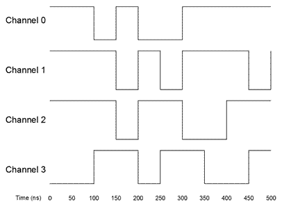
The Graphical User Interface and
Corresponding Signal Output:
The BeagleBone
Black:
Final Presentation: Click here to download my presentation in PowerPoint and pdf format of my poster.
Final Report: We
are in the process of publishing a paper on our work. It shall be uploaded here soon.
About Me: I am entering my senior year as a physics major at Mount Holyoke College in South Hadley, MA.
Useful
Links:
American Physical Society Statements on Ethics