1. Carbon Nanotube (CNT) Deposition

When I began the project, graduate student Jinkang Lim was determining the repeatability and reliability of carbon nanotube deposition on single mode 
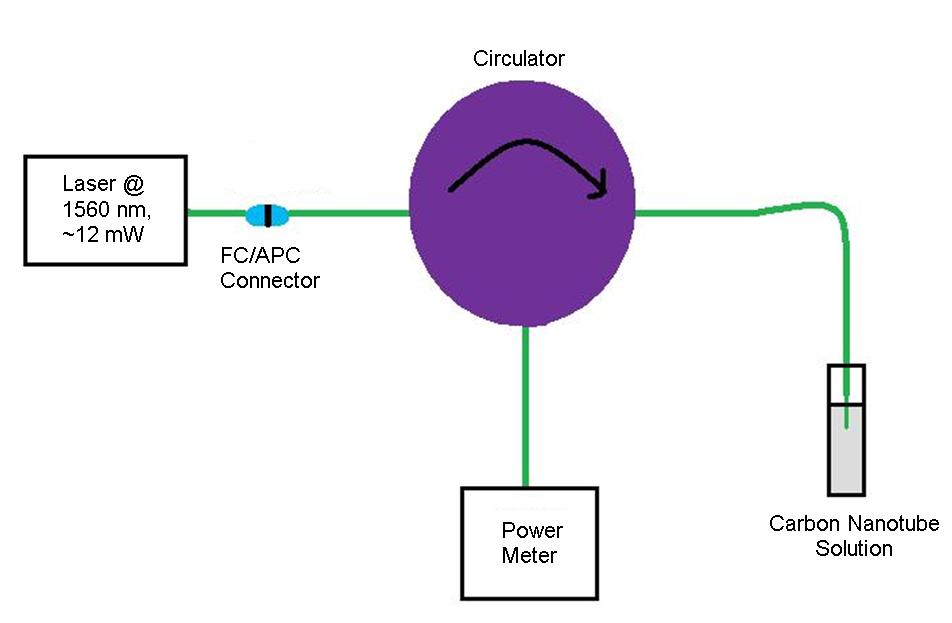
fiber (SMF). In this process, SMF is attached to a circulator and dipped in a solution of single-walled carbon nanotubes and ethanol with laser light being put through the fiber. As a result, a temperature gradient is created in the solution and nanotubes begin to attach to the tip of the SMF. Due to the Van Der Waals force between the nanotubes, more and more continue to clump onto the SMF tip. Since the nanotubes have a higher index of reflection than the solution, an increasing amount of light will be reflected back through the circulator, which is then measured by a power meter. An ideal graph shows a sudden increase of power in the shape of a plateau with time on the x-axis and power on the y-axis.

After repeating this process with different solutions and at different powers, it was determined that a wavelength of about 1560 nm at about 12 mW of power provided for sufficient deposition. The solution was about 12 mL of ethanol with an extremely small amount of nanotubes. The solution was then sonicated for thirty minutes in order to fully mix the solution for the deposition process, which takes about 15 minutes. When the deposition process was refined and finalized, it was time to start building the laser. (1)

A diagram of the setup used in the deposition process.

A photo of an SMF tip viewed head-on with deposition on the central core. The black smudges are the carbon nanotubes.

2. Building the Carbon Nanotube Fiber Laser (CNFL)

The components of the laser include a wavelength division multiplexer (WDM) which couples two different waves together, erbium doped fiber (EDF) to act as the gain medium, an isolator to prevent reflection, a 90/10 splitter in order to create an output and the connector with nanotubes deposited on the end to act as the saturable absorber which generates the mode-lock. See the links on the left in order to learn more about the physics of the laser.

The CNFL Jinkang, Tyler and I built. It is very portable and durable.

A diagram of the laser setup.

In order to build the laser, we put all of the components together and then proceeded to cut back fiber until the desired repetition rate of 100 MHz was reached. We began with about 4 m of fiber, and cut back to 2 m. In the end 48 cm of EDF were used.

We reached our goal of a 100 Mhz repetition rate laser!

After the laser was successfully built and working, we noticed that its bandwidth was very small at about 6 nm. We hoped that cutting back fiber would increase the bandwidth, but no dramatic changes were seen. As a result, we decided to make adjustments to the nanotubes in order to see if they were limiting the bandwidth. In the process of doing this the laser broke, but despite this sacrifice, new information regarding carbon nanotubes in a laser cavity was revealed.

3. Depositing on Photonic Bandgap Fiber (PBGF)

The next phase of my project involved exploring different possibilities regarding the deposition process. The first variability being tested is deposition on PBGF instead of SMF. PBGF is similar to SMF except that around its central core is a honeycomb of holes. Due to these holes, various gases, or in our case nanotubes, can be placed in the fiber dramatically changing its properties. In this new project, we hope to see if the nanotubes are drawn up into the fiber, and if the fiber can become a successful component in a CNFL. (2)

This is an example of a PBGF tip viewed head-on.

The source for photo is http://www.kirbyresearch.com/images/etc/pbgf

Since PBGF is so different from SMF, the splice between the two is extremely fragile. As a result, the deposition process was almost impossible since movement of the fiber meant the splice would instantly break. After intense amounts of frustration, and attempting to use a bare fiber connector, we decided to try a new method for measuring deposition.

4. Determining Deposition on an Angled Fiber Cleave

Due to the splice between SMF and PBGF, the reflected light from the splice overshadowed any change in reflected light. Because of this, Kristan Corwin had an inspired idea concerning a new method to determine deposition. Instead of looking at the reflected light, a photo-detector in conjunction with a voltmeter was placed directly underneath the solution in order to measure the transmitted light. Due to its new placement, the transmitted light should decrease dramatically in the shape of a plateau, opposite to what we expected in the reflection method.

The new setup used a photo detector underneath the solution. The original setup measured the reflected power using a circulator.