Kansas Light Source Upgrade
by Scott Palmiter
Partner: Jason Tackett
Supervisor: Dr. Zenghu Chang
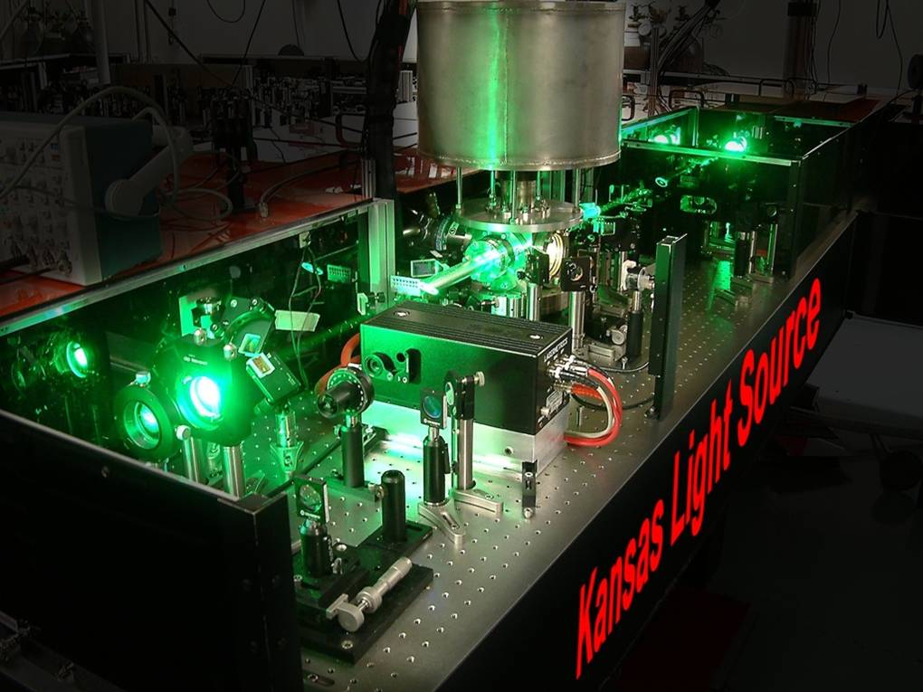
In the James R. Macdonald Lab in the Physics Department at Kansas State University there is a laser facility called the Kansas Light Source. The Kansas Light Source (KLS) is an “ultrafast, high intensity laser facility” established by Dr. Zenghu Chang and his research group in 2001. The KLS is used for “studying the fastest dynamics in atoms, molecules and other matter under the influence of strong electric fields” and currently serves experiments within the facility along with five other lab groups within the Macdonald lab. The Kansas Light Source laser system actually produces extremely short pulses that are as short as 8fs which is on the order of the fastest molecular oscillations. Current operating conditions include pulse duration of 25fs and pulse energy of 2.5mJ at a wavelength of 790nm.
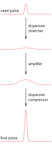
The KLS works through a very intricate process of
stretching, amplification, and compressing to reach the final output beam.
First, seed pulses with 1nJ of energy at 10fs are stretched to 100ps, lowering
the amplitude of the infrared beam, to avoid damag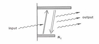 ing
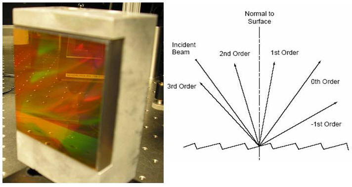
the amplification media. The beam is stretched out in time by using holographic
gratings. Gratings are made up of thousands of tiny grooves (1200grooves/mm in
our case). As light reflects off of the grooves, it is spread out spatially.
Using a pair of gratings the beam can be spread out spectrally and then combined
back together such that the time duration of the beam is changed. The
amplification media in our case is a Ti:sapphire crystal. A pump laser creates a
population inversion within the crystal in which there are more atoms in excited
states than in the ground state. As the 790nm beam passes through the crystal,
it stimulates the atoms. The atoms then eject photons as they lower to the
ground state that join and amplify the 790nm beam. With each successive pass
through the crystal, there are more photons within the infrared beam, causing
more photons to be ejected. There are fourteen passes in total, amplifying the
790nm beam to 2.5mJ. The infrared beam is then compressed back down to 25fs
using another pair of gratings.
ing
the amplification media. The beam is stretched out in time by using holographic
gratings. Gratings are made up of thousands of tiny grooves (1200grooves/mm in
our case). As light reflects off of the grooves, it is spread out spatially.
Using a pair of gratings the beam can be spread out spectrally and then combined
back together such that the time duration of the beam is changed. The
amplification media in our case is a Ti:sapphire crystal. A pump laser creates a
population inversion within the crystal in which there are more atoms in excited
states than in the ground state. As the 790nm beam passes through the crystal,
it stimulates the atoms. The atoms then eject photons as they lower to the
ground state that join and amplify the 790nm beam. With each successive pass
through the crystal, there are more photons within the infrared beam, causing
more photons to be ejected. There are fourteen passes in total, amplifying the
790nm beam to 2.5mJ. The infrared beam is then compressed back down to 25fs
using another pair of gratings.
The Kansas Light Source is utilized for many experiments around the Macdonald lab running almost twenty-four hours a day, seven days a week. Beam time is at a premium with so many users. It was estimated that roughly on 60 percent of usage requests were fulfilled in spring of 2006. This, coupled with the fact that the number of people working in the lab needing laser beams is increasing, makes additional beams necessary. This is where the Kansas Light Source Upgrade comes in. The upgrade includes a second amplifier and compressor that will be able to provide another laser beam. After the first seven passes in the original compressor the beam is separated, part of it is sent on through the rest of its bounces. The other part is brought to the new amplifier for its last seven passes and is compressed in a new compressor.
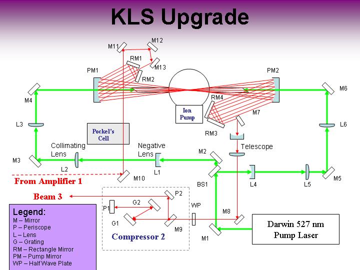
Pump System
The pump system is composed of the Darwin 527nm
Pump Laser and optics used to obtain a 1 mm spot size at the crystal location
from both sides. Using a 50/50 beam splitter, the beam will be sent into the
crystal from both sides. The pump laser can not be converged by just using one
converging lens. In order to get a 1 mm spot size, we must first enlarge the
beam with a telescope (up to 1” in our case), and then make it smaller.
Figure 1: Achieving Desired Beam Size
The appropriate focal lengths and separation between the lenses of the telescope were determined using the following method:
f1= focal length of lens 1 i = image size
f2= focal length of lens 2 r = beam diameter
d = distance between lens 1 and lens 2
Knowing the beam diameter of the pump laser, we determined lens L1 and L2 to have focal lengths of -60mm and 300mm, respectively. The separation between the two is 240mm. The third collimating lens L3 has a focal length of 1000mm and is mounted on a translation stage to provide fine adjustment. The other path using L4, L5, and L6 is identical in necessary specifications. These important distances are illustrated in Figure 9 below. The mirrors M1 – M6 are coated for 527 nm wavelength light. Mirrors M3-M6 are 2” in diameter to ensure the entire beam is reflected.
Note: Space was left next the current location of the pump laser for the addition of a second pump laser.
Certain methods of measuring the laser beam spot size were utilized while building the pump system to check for desired sizes at certain locations of interest.
The first method can be used when the beam is relatively small (smaller than the screen on the CCD camera). First, we came up with a ratio of millimeters to pixels. Figure 3 below is a diagram of the CCD screen. We used known dimensions to find a ratio of 0.01195mm/pixel. Using Scion imaging software, the number of pixels that are covered by the beam can be counted.
Figure 3: CCD Camera Screen
A second method was used for when the beam was too big to fit on the CCD’s screen (i.e. when we are measuring an inch spot size). Instead, the beam was projected onto a screen positioned perpendicular to CCD’s view (Figure 4). The same concept was used as before to find a ratio of unit length per pixel. We did this by first marking references on the screen, a know distance apart. Knowing this distance we could make our ratio. There are two things to be careful of when using this method however. The ratio must be recalculated each time either the camera or the screen is moved. Also, when counting the number of pixels covered by the beam, you must pick a vertical selection of the beam profile. The horizontal diameter is elongated because it is hitting the screen at an angle.
Figure 4: Method of Measuring Beam Size
Amplification System
The amplification system encompasses the optics which directs the seed pulse through the amplifying Ti:sapphire crystal and the chamber which holds the crystal itself. The seed pulse is introduced to the new amplifier by a series of TLM2 mirrors (M10-M13). Directed by the retro mirrors (R1-R4) and pump mirrors (P1 and P2), the beam is sent through the crystal with seven successive passes. The retro mirrors are TLM2’s that are special in that they are rectangular mirrors (2”x1”). The pump mirrors are short wave pass dichroic spherical mirrors that are specially coated to transmit 527nm wavelength light while reflecting 800nm.
Figure 5: Paths of 7 Passes Trough Crystal
After the seven passes in this amplifier the beam is picked off with M7 and sent to the compressor. First however, the beam passes through a telescope that serves two purposes. When the beam exits the amplification system, it is not collimated because of the spherical mirrors. The telescope collimates the beam and also enlarges the beam size so that the gratings are not damaged due to the increased intensity. The chamber that holds the crystal is under vacuum created by an ion pump. The beams enter the chamber through Brewster windows on either side of the crystal with a viewing window on the front. Figure 9 illustrates several critical distances that we have determined.
Compressor System
After the pulse has been amplified, it must be compressed in time as the last step in our amplification process. The compressor consists of a pair of gratings, two periscopes, and a half wave plate. Since the 790nm beam exits the amplifier vertically polarized, the half wave plate is needed to rotate the polarization 90o to achieve maximum efficiency from the gratings. From the half wave plate, the beam strikes the first grating and is diffracted horizontally into different orders. We made the first order hit the second grating as close to the Litrow angle as possible. The second grating collimates the diffracting beam. From here the first order of the second grating is directed to the large periscope P1 that lowers the beam height from 5” to ~3.85”. The beam is then directed back into the grating pair which finishes the compression process. A second periscope P2 raises the beam height back to 5” above the optical table for our final beam.
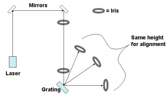
Grating Alignment
The gratings must be aligned such that the grooves are perpendicular to the optical table in every direction. This is done by checking the height of the diffracted orders. First a beam parallel to the table is directed onto the grating and irises set to the same height (5”) are placed at the locations of the diffracted orders (Figure 6). By adjusting the tilt platform, the orders were sent into the irises indicating that the grating grooves were perpendicular to the table in all directions.
Figure 6: Grating Alignment
Periscope Alignment
The periscopes must be aligned such that a beam coming in parallel to the optical table will exit parallel, independent of where it strikes the incident mirror. The large periscope P1 is used to lower the expanded beam and send it back to the grating pair. This periscope was built using 2” square mirrors and normal mirror mounts because there are no 45o adapters. This makes the job of aligning quite difficult. We started with the top mirror, setting the mount at approximately 45o and made sure that the incident beam was reflected straight down, utilizing the holes on the table. Next we added the bottom mirror and used two irises to check the parallelism at the lower beam level. Also we confirmed that the exiting beam is indeed parallel regardless of where the incident beam strikes the top mirror.
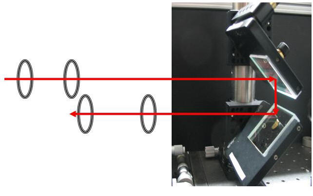
The second, smaller periscope P2 was aligned similarly. However, this periscope contains 45o adapters. With P2 we started with the bottom mirror, setting it at the exiting height of the first periscope (~3.85”). We reflected the beam straight upward, using a plum bob to create a reference point directly above the periscope. Next, we added the top mirror, changing the beam height to 5” and directing in the path illustrated in Figure 8. Irises were again used to check that the exiting beam was parallel to the table. When the periscope is aligned in such a way, the polarization of the beam is changed by 90o - in this case, from horizontal to vertical.
Optimizing the Compressor
After aligning the compressor components, the compressor
must be optimized. First the polarization is changed until the resultant
diffraction orders are at highest power, indicating maximum efficiency (when the
beam is horizontally polarized). This was achieved by monitoring the power of
the zero order while changing the beam polarization with the half wave plate.
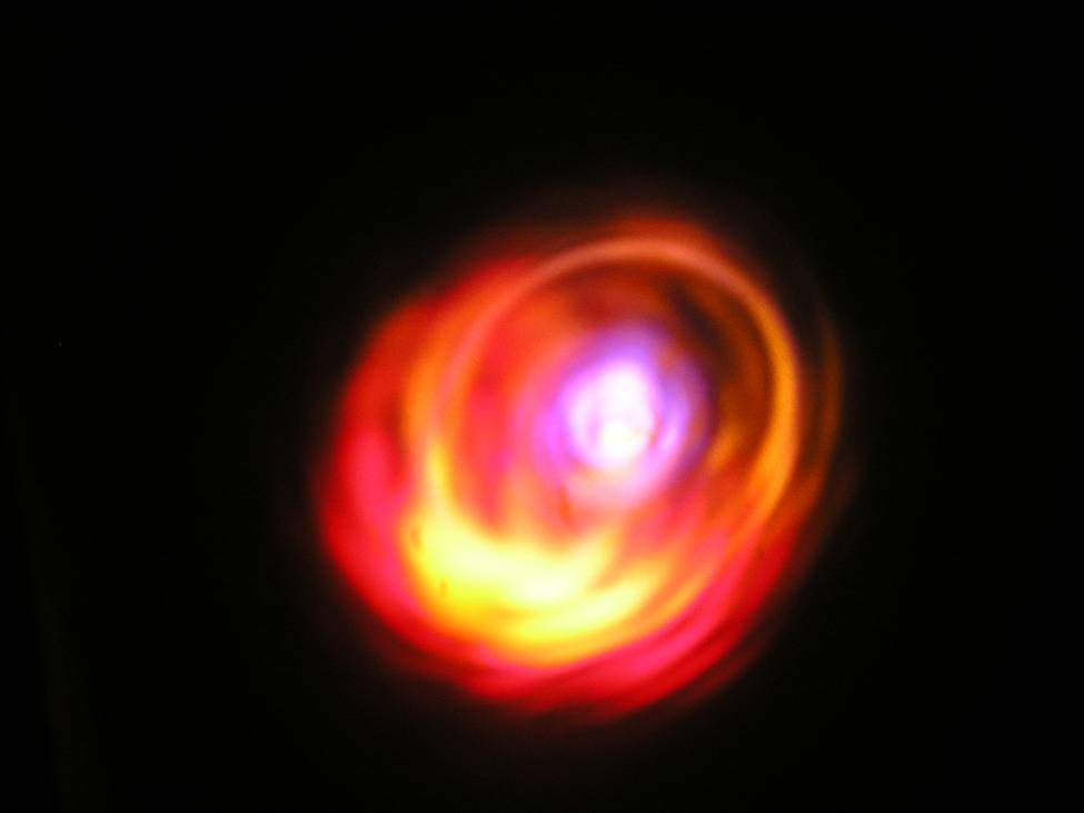
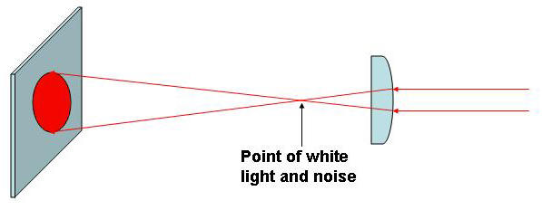
We next optimized the second order dispersion by finding
the best linear grating separation. According to theory, the distance should be
140mm, so we started there. Using a very short focal length lens (30mm) after
the compressor, we generated white light from the amplified beam at the focal
point. White light is created by focusing all beam energy to one point. This
area of high intensity oscillates the air molecules, creating noise. While
changing the distance between the gratings, the amplitude of the white light and
noise level varies. The optimum distance is found when the white light and noise
are at their greatest amplitude.
Third order dispersion is optimized when the gratings are parallel to one another. Ideally the exiting spectrum should be the same as the spectrum prior to compression. To do this, we used a long focal length lens (700mm) to focus the compressed beam onto a CCD camera. Since the spectrum only changes horizontally and not vertically in the gratings, the CCD image is an oval. As the second grating was made more parallel with the first, the horizontal spectrum changed until the image was circular. This means that the horizontal spectrum is at a minimum, ensuring the exiting spectrum is indeed the same size as the incident spectrum. This is confirmed by figure 7 below which shows the two overlapped.
This completes the compressor optimization. The rotation stage settings can be found in table 1 below.
Figure 7: Graph of Spectra of Amplified Beam Before and
After Compression 
Table 1: Rotation Stage Setting in Compressor
|
|
Grating 1 (o) |
Grating 2 (o) |
Periscope (o) |
|
Prior |
126.5 |
123.9 |
156.5 |
|
Optimized |
126.5 |
124.2 |
157.5 |
Pulse Duration Estimate
After optimizing the compressor, we used the FROG (Frequency Resolved Optical Gating) system to estimate the pulse duration and spectral width. Our pulse was approximately 29.91fs in duration with a spectral width of 44.84 nm. This is comparable to the current properties of the existing beams in the KLS.

Figure 9: Known Distances
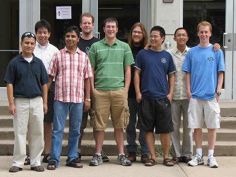
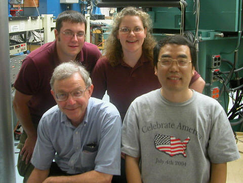
Some of the KLS Research Group:
American Physical Society Statements on Ethics
Diffraction Gratings Brochure. Optometrics Corporation. 28 July 2006. PDF File. <http://www.optometrics.com/prod/spectro/gratings/ gratingbrochure.pdf>