Part 1: laser injuries
The eye:
The eye is the most sensitive body organ to laser injury. Because the eye is a light receptor and lasers produce light of extreme brightness, exposure of the eye to laser light can cause serious and lasting damage. Before going on to eye-damage mechanisms, lets review the structure of the eye.
The cornea is the transparent layer of tissue covering the eye. Damage to the outer cornea may be
uncomfortable (like a gritty feeling) or painful, but will
usually heal quickly. Damage to deeper
layers of the cornea may cause permanent injury.
The lens focuses light to form images onto the retina. Over time, the lens becomes less pliable, making it more difficult to focus on near objects. With age, the lens also becomes cloudy and eventually opacifies. This is known as a cataract. Every lens develops cataract eventually.
The part of the eye that provides
the most acute vision is the fovea
centralis (also called the macula lutea). This is a relatively small area of the retina (3 to 4%) that provides the most detailed and acute vision
as well as color perception. This is why
eyes move when you read or when you look as something; the image has to be
focused on the fovea for detailed perception. The balance of the retina can
perceive light and movement, but not detailed images (peripheral vision).
If a laser burn occurs on the
fovea, most fine (reading and working) vision may be lost in an instant. If a laser burn occurs in the peripheral
vision it may produce little or no effect on fine vision. Repeated retinal burns can lead to blindness.
Fortunately the eye has a
self-defense mechanism -- the blink or aversion response. When a bright light hits the eye, the eye
tends to blink or turn away from the light source (aversion) within a quarter
of a second. This may defend the eye
from damage where lower power lasers are involved, but cannot help where higher
power lasers are concerned. With high
power lasers, the damage can occur in less time than a quarter of a second.
Symptoms of a laser burn in the
eye include a headache shortly after exposure, excessive watering of the eyes,
and sudden appearance of floaters in
your vision. Floaters are those swirling
distortions that occur randomly in normal vision most often after a blink or
when eyes have been closed for a couple of seconds. Floaters are caused by dead cell tissues that
detach from the retina and choroid and float in the
vitreous humor. Ophthalmologists often
dismiss minor laser injuries as floaters due to the very difficult task of
detecting minor retinal injuries. Minor
corneal burns cause a gritty feeling, like sand in the eye.
Several factors determine the degree of injury to the eye
from laser light:
- pupil
size -
The shrinking of pupil diameter reduces the amount of total energy
delivered to the retinal surface.
Pupil size ranges from a 2 mm diameter in bright sun to an 8 mm
diameter in darkness (night vision).
- degree
of pigmentation - More pigment (melanin) results in more heat absorption.
- size
of retinal image - The larger the size, the greater the damage because
temperature equilibrium must be achieved to do damage. The rate of equilibrium formation is
determined by the size of the image.
- pulse
duration
- The shorter the time (ns versus ms), the greater the chance of injury.
- pulse
repetition rate - The faster the rate, the less chance for heat dissipation and
recovery.
- wavelength - determines where the energy deposits and how much gets through
the ocular media.
Eye Absorption Site vs.
Wavelength
Different
wavelengths of light are absorbed in different parts of the eye. Visible light
reaches the retina for image perception.
Other wavelengths interact with eye tissue differently. Where the laser
energy will be absorbed in the eye depends on the light’s wavelength.
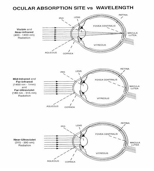
Notice that visible and near infrared light are focused onto the retina by the eye’s lens. This makes the eye much more sensitive to injury from light in this wavelength range (400 nm – 1400 nm) because the focusing by the lens increases the power density in the laser beam.
The damage mechanisms are similar
no matter where the light is absorbed.
The basic types of damage are thermal burns, photochemical reactions,
and acoustic shock. The last mechanism,
acoustic shock, is caused by high-intensity short-pulse lasers when the laser
light causes a sudden vaporization of tissue which then causes a shock wave to
spread, tearing other tissues in the eye. Photochemical reactions either cause cloudiness
in eye tissues or a loss of light sensitivity.
Near UV light that is absorbed in the lens
The skin:
Lasers can harm the skin via
photochemical or thermal burns.
Depending on the wavelength, the beam may penetrate both the epidermis
and the dermis. The epidermis is the
outermost living layer of skin. Far and
Mid-ultraviolet (the actinic UV) are absorbed by the epidermis. A sunburn (reddening
and blistering) may result from short-term exposure to the beam. UV exposure is also associated with an
increased risk of developing skin cancer and premature aging (wrinkles, etc) of
the skin. Longer wavelengths of
light are mostly a source of thermal burns to the skin. Burns can be second or
third degree, but are rarely serious because peoples
reflexes cause them to move out of the way of the light.
Light wavelengths and injury summary:
The part of the electromagnetic spectrum relevant to lasers is divided into seven wavelength regions as follows:
Ultraviolet C: 100-280 nm B: 280-315 nm A: 315-400 nm
Visible 400-760 nm
Infrared A: 760-1400 nm B: 1400-3000 nm C: 3000-106 nm
Ultraviolet C radiation is responsible for photokeratitis of the cornea and erythema of the skin (sunburn).
Ultraviolet
B
radiation is responsible for photokeratitis of the
cornea, skin cancer, and accelerated aging.
Ultraviolet A radiation is responsible for photochemical cataracts, pigment darkening and skin burn.
Visible radiation is responsible for photochemical and thermal retinal injury, photosensitive skin reactions and skin burn.
Infrared A radiation is responsible for cataracts and retinal burns and skin burns.
Infrared B radiation is responsible for corneal burns, cataracts, damage to the aqueous humor, and skin burns.
Infrared C radiation is responsible for corneal and skin burns.
Part 2: Laser Safety
Laser power classes:
Lasers can be divided into four
basic classes according to their potential to inflict harm on the user or
bystanders.
CLASS I LASERS are
low-powered and do not emit hazardous radiation under normal operating
conditions because they are completely enclosed. Class I lasers are exempt from
any control measures. Equipment, such as laser printers and laser disc players,
are examples of this class.
CLASS II LASERS emit accessible visible laser light with power levels less than 1 mW radiant power and are capable of creating eye damage through chronic exposure. The human eye blink reflex, which occurs within 0.25 seconds of exposure to the Class II laser beam, provides adequate protection. It is possible to overcome the blink response and stare into the Class II laser long enough to damage the eye. Class II lasers are exempt from any control measures. Some visible continuous wave Helium-Neon lasers and some laser pointers, are examples of Class II lasers.
CLASS IIa LASERS are special purpose lasers that emit accessible visible laser light with power levels less than 1 mW radiant power and are not intended for viewing. This class of lasers causes injury when viewed directly for more than 1,000 seconds. Class IIa lasers are exempt from any control measures. Grocery store scanners are examples of Class IIa lasers.
CLASS IIIa LASERS are systems with power levels of 1 to 5 mW that normally would not produce a hazard if viewed for only momentary periods with the unaided eye. They pose severe eye hazards when viewed through optical instruments (e.g., microscopes, binoculars, or other collecting optics). Class IIIa lasers must be labeled. A warning label shall be placed on or near the laser in a conspicuous location and caution users to avoid staring into the beam or directing the beam toward the eye of individuals. Some visible continuous wave Helium-Neon lasers and some solid state laser pointers are examples of Class IIIa lasers.
CLASS IIIb LASERS are systems with power levels of 5 mW to 500 mW (CW) and some pulsed lasers. These lasers will produce an eye hazard if viewed directly. This includes specular reflections. Administrative, Engineering, and PPE control measures are required. (Especially laser safety glasses!)
CLASS IV LASERS are systems with
power levels greater than 500 mW and many pulsed
lasers. These lasers will produce eye, skin and fire hazards. This includes
specular or diffuse reflections. Administrative, Engineering and PPE control
measures are required. (Especially
laser safety glasses!)
Lasers in the
|
Location |
Name |
Characteristics |
Designations |
Goggles |
|
KLS |
Verdi |
532nm, 6W, CW |
|
Brown |
|
KLS |
FemtoPro |
800nm, 5 nJ/pulse @ 10 fs/pulse |
IR-A, Class IV |
Pink |
|
KLS |
Evolution 30 |
527 nm, 20 mJ/puls, 100 ns/pulse |
|
Brown |
|
KLS |
KLS |
800 nm, 3 mJ/pulse @ 25 fs/pulse |
IR-A, Class IV |
Pink |
|
KLS |
Hollow fiber |
800 nm, 1 mJ/pulse @ 6 fs/pulse |
VIS-IRA, IV |
Blue |
|
EBIS |
CSU L1 |
780 nm, 15 mW, CW |
IR-A, Class IIIb |
Pink |
|
EBIS |
CSU L2 |
1529 nm, 15 mW, CW |
IR-B, Class IIIb |
Grey |
|
EBIS |
CSU L3 |
730-820 nm, 300 mW, CW |
IR-A, Class IIIb |
Pink |
|
EBIS |
CSU Pump |
532 nm, 6W, CW |
|
Brown |
|
EBIS |
CSU CO2 |
10 μm, 50 W, CW |
IR-C, class IV |
Grey |
|
MOTRIMS |
Master |
780 nm, 30 mW, CW |
IR-A, Class IIIb |
Pink |
|
MOTRIMS |
TDA |
780 nm, 350 mW, CW |
IR-A, Class IIIb |
Pink |
|
MOTRIMS |
Repump |
780 nm, 15 mW, CW |
IR-A, Class IIIb |
Pink |
|
MOTRIMS |
L2 |
1529 nm, 25 mW, CW |
IR-B, Class IIIb |
Grey |
|
MOTRIMS |
EDFA |
1529 nm, 25 mW, CW |
IR-B, Class IIIb |
Grey |
|
LUMOS |
Pump laser |
1300 nm, 10 W, CW |
IR-A, Class IV |
Grey |
|
LUMOS |
CrFosterite |
1250 nm, 2.5 nJ/pulse @ 20-40 fs |
IR-B, Class IIIb |
Grey |
|
LUMOS |
Ando |
1500 nm, 10 mW, CW |
IR-B, Class IIIb |
Grey |
|
LUMOS |
EDFA |
1500 nm, 500 mW, CW |
IR-B, Class IIIb |
Grey |
|
LUMOS |
Santec |
1500 nm, 10 mW, CW |
IR-B, Class IIIb |
Grey |
|
LUMOS |
CO2 |
10 μm, 35 W, CW |
IR-C, Class IV |
Grey |
|
LUMOS |
HeNe |
632 nm, 8 mW, CW |
|
Blue |
Personal Protective Equipment:
Personal protective equipment (PPE) is intended to protect
you from hazardous exposure. For skin
exposure to laser light, the appropriate PPE is clothing that will cover any
skin areas that might be exposed to laser light (long sleeves, gloves, shoes,
hoods, etc.). To avoid injury to the
eyes from laser light, you need appropriate protective goggles.
The purpose of laser protective eyewear is to filter out the laser frequencies while maximizing vision from ambient light. To select the right laser goggles, you need to know the wavelength of the radiation and what attenuation factor is needed to make the laser safe for your eyes. Knowing the wavelength and duration of exposure, you can look up the maximum permissible exposure from the ANSI tables. The optical density of the glasses needed is the attenuation required to reduce the power density in the beam to or below the maximum permissible exposure.
The optical density (O.D.) of a filter is a measure of the
light transmitted through the filter.
O.D. is defined as the negative log of the filter transmission (O.D. =
-log10 (transmitted power/incident power)); thus an O.D. of 4
indicates that 0.01% of the incident light in the stop band of the filter will
be transmitted through the filter and that 99.99% will be stopped by the
filter.
To determine the required optical density for glasses for
safe operation of a laser, use the output power of the laser and the maximum
permissible exposure (MPE), or exposure limit, to radiation under the laser’s
operating conditions. The required O.D.
for safety glasses is given by: O.D. = log10 (laser output/exposure
limit) (*note that the laser output and exposure limit must have the same
units.)
Always inspect glasses for damage before wearing them. Also
keep in mind that glasses can themselves be damaged by the laser exposure and
loose some of their protective capacity if the power of the laser is above
their damage threshold.
Another thing to be aware of when selecting laser
protective eyewear is how the transmission of the goggles will effect your ambient light vision. It is possible for the goggle to block your
ability to read instruments or see controls on your apparatus. And example would be a goggle that blocks
visible red light as would be used for a HeNe laser
or the KLS short-pulse beam would keep you from seeing red LED’s. A situation like this requires the user to
develop the discipline not to remove his protective glasses to read the
instrument. In cases where it is
impossible to do an experiment because the laser goggles interfere too much
with vision, remote monitoring of the experiment can be arranged using video
cameras and monitors.
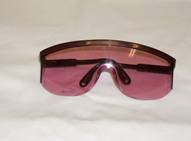
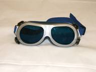
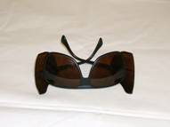
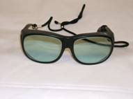
These are the
laser-protective goggles that we keep in the
|
Designation |
Use |
Optical density at wavelength |
Limitations |
Picture |
|
Pink |
KLS long pulse, MOT trapping, CSU L1 |
4+ @ 755-780 nm, 7+ @ 780-840 nm, 4+ @ 840-855 nm |
|
|
|
Blue |
KLS short pulse, HeNe, diodes CO2 |
4+ @ 630-690 nm, 7+ @ 690-970 nm, 5+ @ 970-1100 nm, 5+ @ 10,600 nm |
Blocks all visible red light, including red LED’s |
|
|
Brown |
KLS + pump, KLS 2nd harmonic, KLS 3rd harmonic, CO2 |
9+ @ 190-520 nm 7+ @ 520-532 nm 3+ @ 710-750 nm 5+ @ 750-850 nm 7+ @ 850-1080 nm 7+ @ 5,000-11,000 nm |
Blocks visible blue LED’s |
|
|
Grey |
LUMOS all CO2 |
3+ @ 850-900 nm 4+ @ 900-950 nm 5+ @ 950-1000 nm 7+ @ 1000-1600 nm 5+ @ 1600-2400 nm 5+ @ 2,940-10,600 nm |
|
|
Administrative Controls:
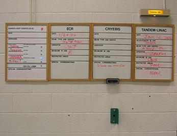
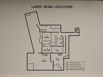
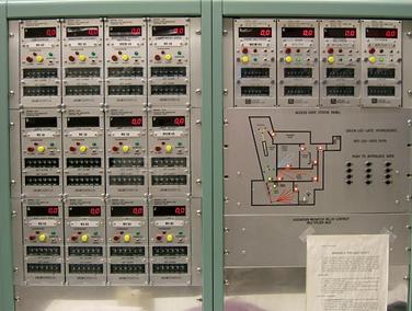
A variety of warning devices have been installed in the Macdonald Laboratory to make users aware of potential hazards from laser light. On entering the lab you will find a series of status panels just inside the door. The panel to the far left indicates where the pulsed beam from the KLS is in use in the lab. A map on the west wall of the control room shows the same information. The lighted LED’s on both boards indicate where the laser is in use. If you are going into any of those areas, you will need to have appropriate laser protective goggles.
Laser
status map in the control room showing that KLS beam is being sent to the
square-room COLTRIMS experiment. Status
board at lab entrance showing the van de Graff is in operation and that KLS
light is being sent to the Square-room COLTRIMS area.
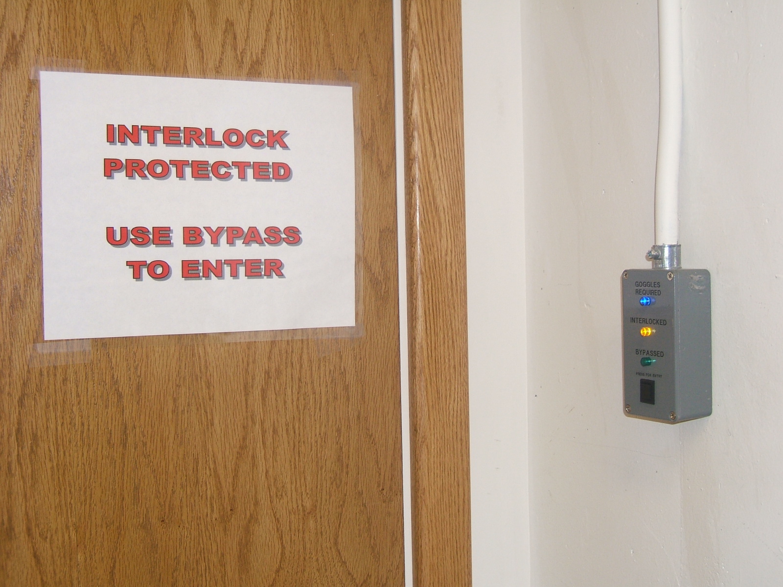
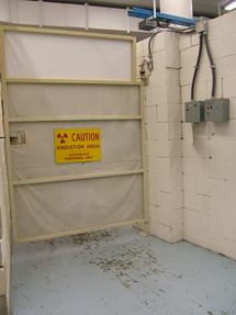
Each area where class IV lasers are in use also has an opaque barrier separating it from the rest of the lab. The passage way through the barrier (door, gate, etc.) has on it an interlock system such that the laser will be turned off in the area if the door is opened. These interlocks are administrative controls (not engineering controls) because they can be easily defeated without shutting down the laser system. The purpose of the interlocks is to protect inexperienced people from laser injuries. Someone doing an experiment with the pulsed laser has to be able to get into and out of the area without shutting down the laser, so there are bypass controls on the door interlocks. The assumption is that if a person knows how to bypass the interlock, he will know to have put on appropriate vision protection before going into the area. The bypass is generally accomplished by pushing a button on a control box next to the interlocked passage way. You should only bypass an interlock and go into an active laser area if you know what hazards exist in the area and you are wearing the proper personal protective equipment (laser goggles.)
Interlock
control at the KLS entrance. The
interlocked door is the innermost door of an air lock that helps to
maintain constant temperature in the KLS for laser stability. The outer
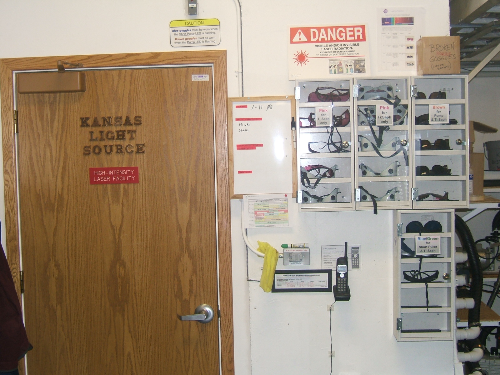
door of the air lock is shown below along side the laser goggle storage. To
bypass the interlock, you push the black button at the bottom of the box. Interlock
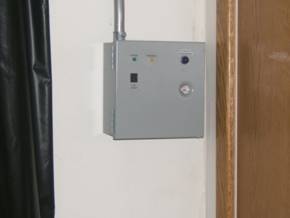
bypass box at the EBIS area control gate.
The blue lamp at the upper right-hand corner indicates the laser
status (currently off.) Pushing the
“bypass: button at the left of the box will override the interlock for a
period of 90 seconds, during which the gate can be opened without
interrupting the experiment in progress.
It
is always the user’s respons
Some of the controlled laser areas have moveable curtains to act as a secondary barrier (LUMOS Square-Room COLTRIMS). These barriers are in place to keep laser light from getting out and exposing unprotected personnel when the doors are being opened and closed. The curtains should always be kept drawn when the laser is in operation.
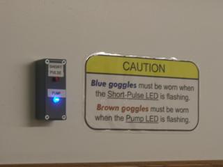
The KLS laser lab has an additional warning indicator to tell users which type of goggles are needed inside the lab under current operating conditions. This display is visible above the barrier in front of the KLS main entrance. There are two lamps on the display, one red, the other blue. These lamps indicate is special conditions exist inside the lab. If the RED lamp in on, the short-pulse fiber is in use, and users must wear the blue or green colored goggles that block out all of the visible red spectrum. If the blue lamp is light, as in the picture below, the green pump laser is uncovered inside the lab and users will need to wear the brown colored goggles. If neither light is on, then the pink NIR goggles will provide adequate protection.
Safety
goggle storage outside KLS Different
safety goggles are needed inside the KLS depending on what machines are in
use. The goggles are kept sorted in
the storage cabinets outside the lab so that users can easily get the
appropriate eye protection. You can
use the phone on the wall to call into the lab to talk to someone
inside. The button to the left of
the phone rings a door bell if you need someone to come out to assist you. Information display outside KLS. The
lights tell you if special conditions exist inside the laser lab. The blue lamp shown lit indicates that
users need to wear brown goggles because the pump laser is uncovered. If the red light is on, then short pulses
are being generated which require the use of the blue goggles. When both lamps are off the pink goggles
may be used.
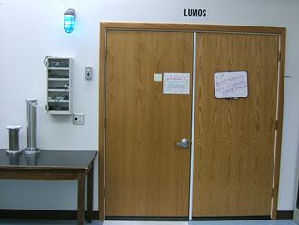
Blue warning lights are turned on outside of laser areas
when the laser is turned on to indicate that the laser is operating. The blue
light is one of the standard hazard warnings in the
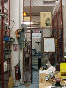
High voltage cage at EBIS with amber warning light. Entrance to LUMOS lab. The blue light outside the door indicates
that the IR lasers are operating inside the lab. Safety goggles for the IR-B band are
stored in the cabinet below the warning light.
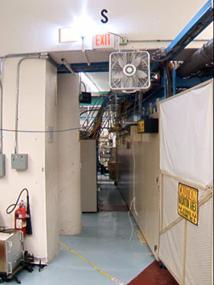
White strobe warning for low oxygen level. Personnel should leave the area
immediately in case of white strobes, which either indicate a fire alarm or
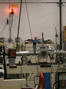
low oxygen levels. View of LINAC common beam line showing
high radiation level alert. All
personnel should leave the area when this light is on.
Engineering Controls:
Certain
of the class IV lasers in use in the
Ionizing radiation:
Some
of the personnel control gates in the
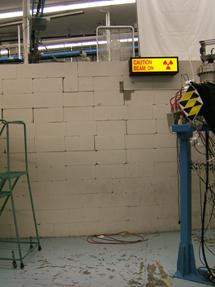
The
control gate between the LINAC hall and the ECR (left) can be shut either
for laser hazards or for penetrating radiation generated by ion beams. The “beam on” light shown at right lets you
know if ion beam is going into the LINAC area. You still need to check the radiation
monitor panel in the control room to see if there is a radiation hazard.
When a lab user comes to a closed control gate, it is the users respons
Radiation
monitor display in the control room.
Each readout is the radiation dose rate at
one of the area monitoring detectors in the lab. The map at lower right shows the
locations of the detectors and the location and status of personnel control
gates. A red LED on the map
indicates there is no interlock for radiation on the gate. A green LED indicates an active gate
interlock tied to the van de Graff accelerator.
Part 3: Lab safety
Compressed Gas
Safety
Hazards from compressed gases:
- Cylinder weight: A cylinder that falls over can break equipment or injure personnel. Cylinders need to be secured at all times so that they can not fall over.
- Gas volume: A full cylinder can contain 5,000 liters of gas. A sudden discharge of the gas would displace air from the work area. Thus, even inert gases like helium or argon represent asphyxiation hazards if the gas is released into a closed space.
- Gas hazards: Gases in cylinders can be toxic or flammable. In the Macdonald lab, we work with CO, which is deadly at a concentration of 100 p.p.m. Accidental discharge of even a small amount of such gas into a closed room would present a serious health hazard. We also have flammable or explosive gases like hydrogen, methane, and acetelene. These gases need to be kept away from sparks or flames. A special hazard is silane, which burns spontaneously in contact with air. Special measures are needed to purge silane from gas manifolds so that it does not cause a fire.
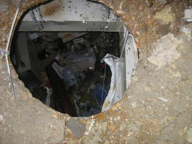
- Cylinder energy: considerable mechanical energy is stored in the compressed gas in a cylinder. If an accident breaches the cylinder valve, that mechanical energy is released as thrust. The cylinder can accelerate to speeds great enough to penetrate concrete walls. The picture below shows a hole in a concrete floor made by a compressed gas cylinder (actually a liquid nitrogen dewar that was allowed to build up too much pressure) that ruptured in use.
Hole in a concrete floor that was mad
by a gas storage cylinder (cryogenic) that ruptured its bottom and jetted
upward through the ceiling and into the room above. The gas discharge also blew out the walls
of the lab where the tank was stored.
Compressed gas Standard Operating Procedures:
1) Storage of cylinders
a) Cylinders should be secured to a wall or other structure so that they cannot fall over.
b) A cylinder that is not in use should have the regulator removed and the safety cap installed over the valve.
c) If a cylinder is empty, it should have a ring put over the safety cap to mark it as empty or be removed from the lab.
2) Moving a gas cylinder
a) Always remove the regulator and install a safety cap before moving a gas cylinder.
b) Transport a cylinder on a four-wheeled cylinder cart with the chain secured so that the cylinder cannot fall off the cart.
3) Connecting a gas cylinder to an experiment
a) Always secure the cylinder to a wall bracket or other support structure before removing the safety cap.
b) Check that the regulator sealing surface and the connector threads are clean and undamaged. If a gasket is needed, make sure it is in good condition. Make sure the regulator is appropriate for the gas you are using.
c) Tighten the regulator to the cylinder using a wrench. Most cylinder nuts are 1 1/8 inch size. There are box wrenches in the lab for this size, or you can use an adjustable wrench. Most nuts tighten by turning the nut clockwise when looking from the regulator towards the cylinder. Left-hand nuts are marked with a grove around their middle, and tighten the other way.
d) Check that the connections to the gas line going to the regulator are not damaged and attach the gas line.
e) The procedure for purging air from the regulator and delivery line will depend on the type of gas and the regulator.
i) Some regulators are tagged as being “for vacuum service”. With these regulators, the whole gas delivery system can be pumped out all the way to the cylinder valve.
ii) For non vacuum service regulators, air is purged by flowing gas through the system
iii) If the gas is toxic, it cannot be purged into the lab. Contact lab technical staff in this case.
f) Check for leaks in the system after all connections are tightened. This is usually done by opening the valve on top of the cylinder to pressurize the regulator. Then the cylinder valve is closed, and the pressure in the regulator is monitored to see if it leaks down. If the gas is toxic, have lab technical staff install and check the gas bottle.
4) Using compressed gas
a) Before opening the valve on a gas cylinder, always make sure that the regulator is shut off. To do this turn the handle in the center of the regulator bonnet fully counter clockwise, either until it stops or until all spring tension on the shaft is released.
b) Open the valve on the cylinder slowly by turning it counter clockwise. Watch the pressure gauge on the inlet side of the regulator to know when the valve is open.
c) Set the desired operating pressure coming out of the regulator by turning the regulator control clockwise while watching the output pressure gauge.
d) When you are finished with your experiment, close the valve on the gas cylinder and turn the regulator pressure control fully counter clockwise.
5) Removing a gas cylinder from use
a) Be sure the valve on the cylinder is closed (clockwise) and that the regulator pressure control is set at its minimum (counter clockwise).
b) If the gas is toxic, it must be purged from the regulator and lines before anything can be opened to air. Contact lab technical staff for help.
c) Remove the delivery line from the regulator.
d) Remove the regulator from the gas bottle. Generally this is done by turning the nut on the regulator adapter counter clockwise. Some regulators have left had threads on them. These are marked by a grove around the flats of the nut. Turn left-hand nuts clockwise to loosen them.
e) Screw the safety cap onto the cylinder. If the cylinder is empty, place a ring over the safety cap.
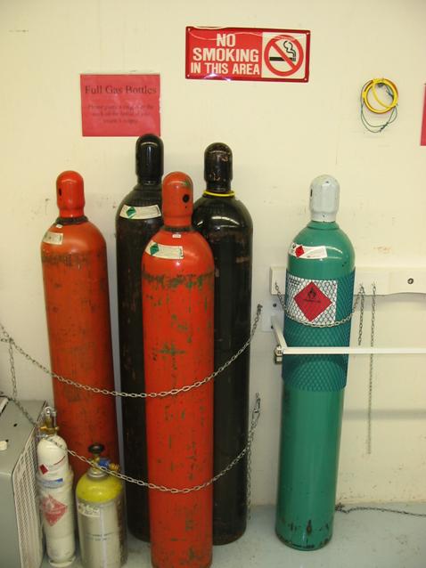
Compressed gas
cylinder storage in the Macdonald Laboratory: Cylinders are kept chained to the
wall so that they cannot fall over.
The safety caps must be secured over the valve of the cylinder
anytime a gas bottle is moved or taken out of service. The black cylinder at the back
right has a yellow ring placed over the cap of the bottle to indicated that
the cylinder has been emptied of gas. The cylinder to the far right
is in a locked storage area that is reserved for toxic gases (the cylinder
contains carbon monoxide.) If you
need a gas from the locked storage areas, you must contact lab technical
staff for setup of the cylinder.
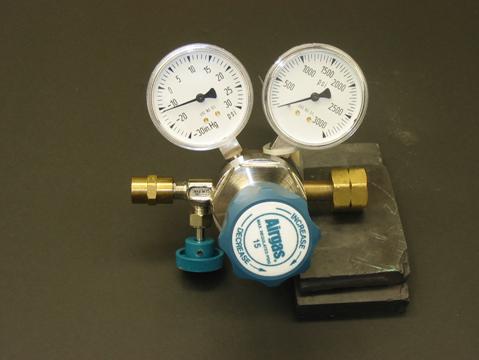
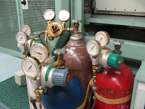
Gas cylinders in
use: These cylinders are all in use at the diode source. The regulators work the same way
irrespective of the type of gas they are installed on. Turning the handle in the center of the
regulator bonnet clockwise will increase the pressure of the gas delivered
to the output line. The pressure
control should always be turned fully counter clockwise before the valve to
the cylinder is opened. It is also
recommended when you finish an experimental run, that you shut off the
regulator by backing out the pressure control counter clockwise. The valves on the bottle always open by turning them
counter clockwise as viewed from above. The pressure gauge nearest the cylinder shows the
pressure in the cylinder, and the gauge farthest from the bottle is the
pressure coming out of the regulator.
Gas cylinder
connections: Different kinds of gases have different fittings at the
cylinder valves where the regulator screws on. The nut on the regulator shown to the
left has left hand threads, as indicated by the notch made around the nut
flats. To remove such a regulator
from a gas cylinder, you must turn the nut clockwise when you are looking
from the regulator towards the cylinder. The most common lab gasses with left-hand threaded
fittings are hydrogen, sulfur hexafluoride, methane, silane,
deuterium, and air. The regulator works in the normal fashion. Turning the control knob clockwise
increases the output pressure and turning it counter clockwise decreases
the output pressure. The gauges are in units of “pounds per square inch” (psi.)