


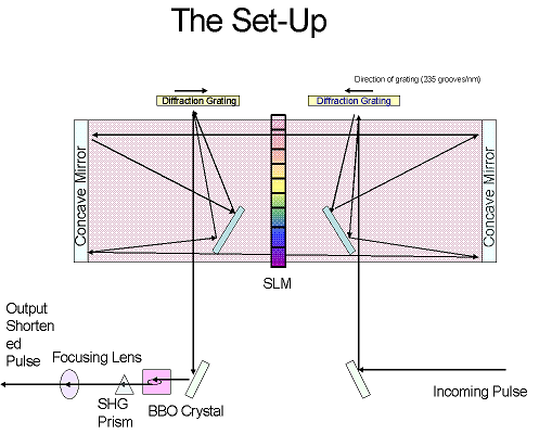
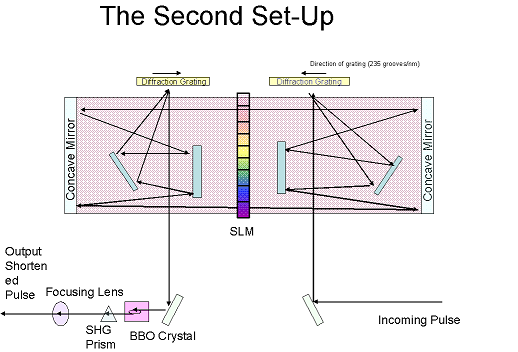
Week 1(That I've been here): In the first week I was quickly inundated with new information. I spend a good deal of time reading over articles concerning our apparatuses like the SLM. I also spent a good deal of time reading about Fourier transforms and how they applied to our work. My graduate students He Wang and Yi Wu informed me that they had aligned the set up in the week before I arrived. Now all we had to do was wait for the rest of the parts to arrive. However, at the end of the week we decided to try a new set up. In the first set-up, the diffraction grating was angled, it was not parallel to the table, so we were losing some efficiency. We decided to aim for a new set up in week two.
.
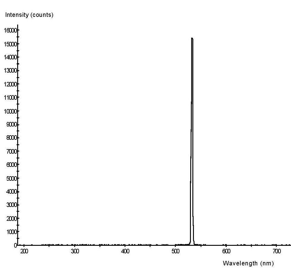
Week 2: Since we're still waiting for the SLM to arrive, we decided to try the second proposed set-up to try to increase the efficiency of the grating. The grating we're currently using has 235 grooves/mm and is aluminum coated. We've also ordered and are waiting on two silver coated grating, which will also maximize efficiency. After adjusting the optics and finding difficulty in reaching a proper alignment, we decided to return to our original set-up which has less components to adjust. Using a green laser ( wavelength=532nm) we tested Set-up one again, to see if our re-alignment was successful. First we utilized an ocean spectrometer and obtained a simple spectrum for green laser light
.
Following this we then used a 10% beam which is a long-pulse
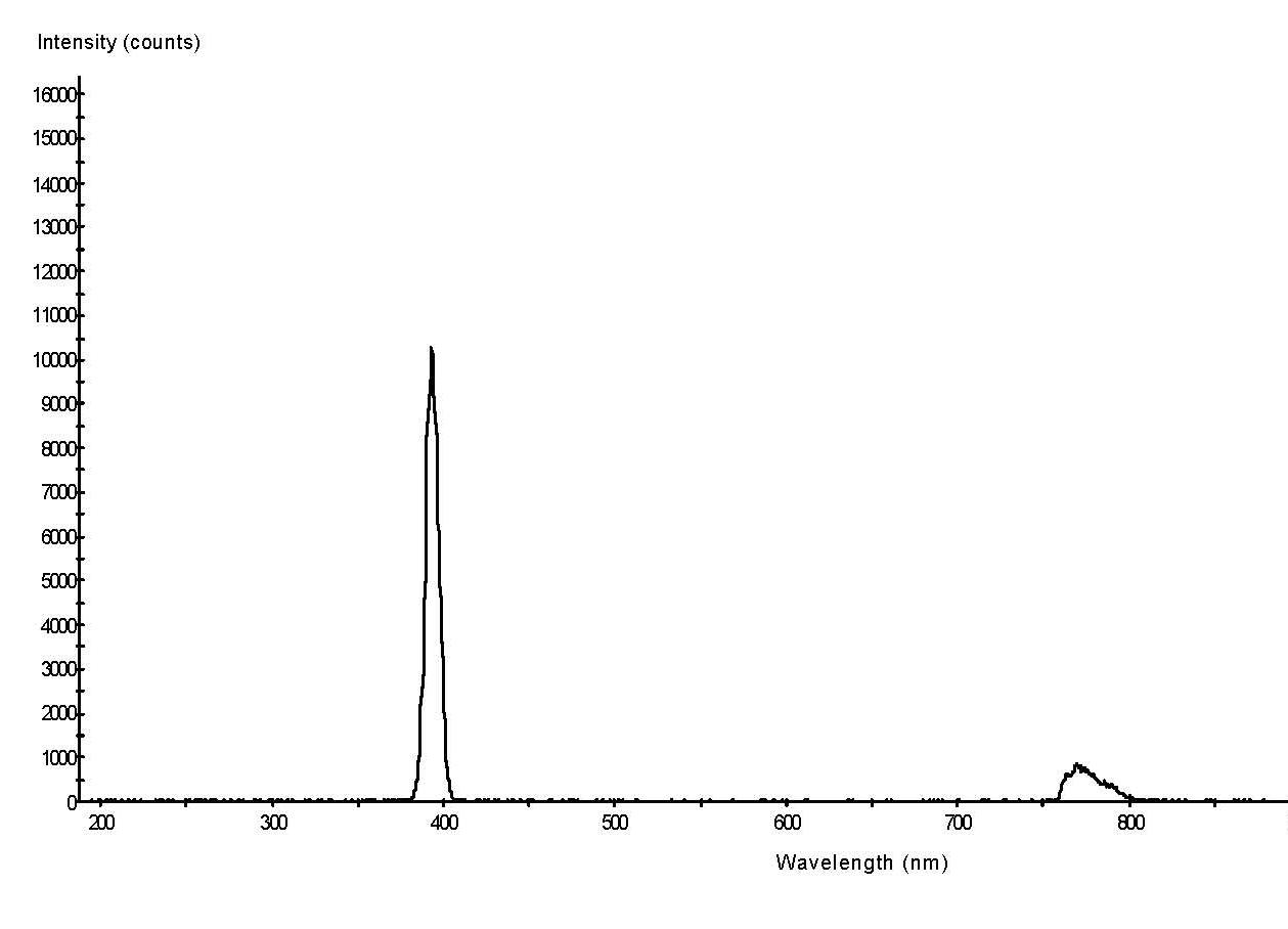
This shows the fundamental wavelength to be around 780nm and the Second Harmonic around 385nm.
Later in the week we tested the efficiency of the system by checking the energy entering the system and the energy leaving the system using a_____(check)
| Trial | Energy In | Energy Out |
| 1 | 13.00 mW | 5.09 mW |
| 2 | 13.35 mW | 5.32 mW |
On average we have about 40% efficiency, so our system is still slightly misaligned. We can also tell because the beam is hitting the outer edges of both grating surfaces. Next week, while we're still waiting for parts to arrive, we'll adjust the alignment of the system until it is more precise.
Week 3: At the beginning of this week, there was not a great deal of alignment to adjust since we were still waiting on parts; a kinetic stage, the silver coated gratings, and the SLM itself. A big set-back came when we learned that the SLM won't arrive until July now, the company says it's been mailed, but it is coming from Germany so the shipping will take quite a bit of time. So on Monday we did a few more minor adjustments, but that was all. On Tuesday the parts still hadn't arrive, so I took the opportunity to try and learn more about the SLM before it arrives. I thought it would be helpful to know some of the basic facts about the SLM.
Liquid Crystal Spatial Light Modulators
SLM-S640, SLM-S640d, SLM-S320, SLM-S320d
Specifications
Single Mask Configuration Dual Mask Configuration
SLM-S640
|
Active area |
64 mm x 10 mm |
|
Number of addressable strips |
640 |
|
Strip size |
97 µm (3.8 mil)× 10 mm |
|
LC orientation (Angle LC director axis ne - strip orientation) |
90 other orientations on request |
|
Transmission (@ 450 nm ... 1100 nm, without polarizers) |
>80 % |
|
Gap |
3 µm (0.12 mil) |
|
LC type |
nematic |
|
Phase modulation Phase shift @ 430 nm Phase shift @ 1600 nm |
approx. 7 p approx. 2 p |
|
Wavelength range |
430 nm ... 1600 nm |
|
Driving voltage |
0 V ... 8 V | 0 V ... 5 V (switchable) 12 bit resolution |
|
Frame buffers |
0 ... 63 |
|
ADC port |
0 V ... 2.5 V 12 bit resolution |
|
Interfaces |
RS232, IEEE1394a (Firewire™) |
|
Trigger in/out |
via optocoupler |
|
Functions |
extended instruction set integrated in firmware (based on SLM-S640/12 instruction set) |
|
Software driver requirements and Programming interface
|
LabView™ 5.1 and higher C-Interface for Microsoft Windows® 2000, Linux (Kernel 2.6.5), Apple Macintosh™ OS X |
|
Mirror (optional) |
enabling operation in reflective configuration (removable for operation in transmissive configuration) |
|
Antireflective coating (optional) |
according to customers specification on request |
|
267001-008-99-11-0107-en JENOPTIK Laser, Optik, Systeme GmbH Business Unit Sensors Goeschwitzer Strasse 25, 07745 Jena, Germany Phone +49 3641 65-3963 Fax +49 3641 65-3573 E-Mail: light-modulators@jenoptik.com Internet: www.jenoptik-los.com It is our policy to constantly improve the design and specifications. Accordingly, the details represented herein cannot be regarded as final and binding. |
Above is just some information from a pamphlet from the JENOPTIK company regard the SLM that we'll be using.
On Wednesday, one of the stages we ordered arrived. So we set to aligning the set up once more. It seems like we may be doing a great deal of tedious alignment, but this alignment is a critical part of our experiment. The optics must be aligned correctly so that we get a spread of 500-1000nm wavelengths passing through the SLM and so that we retain the maximum amount of efficiency and energy. It was difficult to get beam time to work on the set up. On Thursday I spent time acquainting myself with LabView, the program we'll be using to program the SLM. I have a few diagrams from that, but I won't be able to add those to this site until tomorrow. Friday we used the beam over lunchtime and took some good images. Right now we're processing the images, so they won't be up for a day or two. Otherwise, the major work for the week was finally getting one new translation stage and then aligning the system more so we can test it with FROG and MIIPS and be prepared for next week. Summary of FROG and MIIPS will be up shortly as well. The exciting part came on Friday as well when the SLM finally arrived.
Week 4: This week we installed the SLM and the programming to operate it. On Monday we also tested the program and device.
As Promised: Frequency Resolved Optical Gating (FROG) * (Information from http://www.physics.gatech.edu/gcuo/lectures/ Lectures by Rick Trebino and http://www.wikipedia.org )
 is the spectrogram
where g(t-t) is a variable -delay gate function and t is the delay
Without g(t-t), SE(w,t) would simply be the spectrum
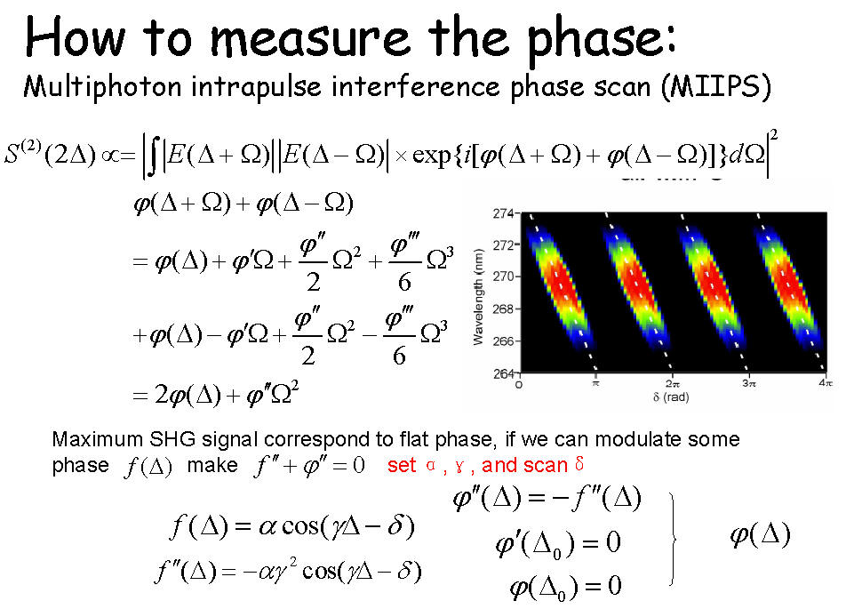
MIIPS is similar with FROG in that a frequency trace is collected for the characterization of the ultrashort pulse. In Frequency-resolved optical gating, a FROG trace is collected through scanning the ultrashort pulse across the temporal axis, and detecting the spectrum of the nonlinear process. It can be expressed as

In MIIPS, instead of scanning on the temporal domain, a series of phase scan is applied on the phase domain of the pulse. The trace of the MIIPS scan is consisted of the second-harmonic spectra of each phase scan. The signal of MIIPS can be written as

Also this week, I began writing a program in LabView that will take results from the SLM, which will be the second derivative of the wavefunction, and convert it to the original function. This will give the original phase of the incoming wavelength. The rest of the week consisted of me continuing to learn how to use LabView. The program is not yet finished, but more information will be coming soon. In the mean time, check out some of my pictures from work. Lab Pictures
Week 5: This week began a little slowly. I am still learning LabView programming and seeing as I have never encountered this type of programming until, the going is a little rough. Hopefully I'll figure it out and have my program written by the end of the week. Also we have begun trial runs of our system and on Tuesday worked out some problems that involved the spectrometer. Wednesday and Thursday involved more learning and practice using LabView. This program is trickier to use than I anticipated, but I am making progress. Here are some pictures obtained in lab using the spectrometer, the SLM and Yi's LabView programming.
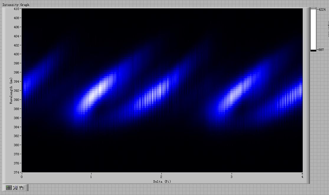
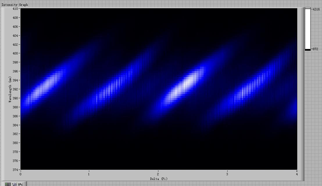
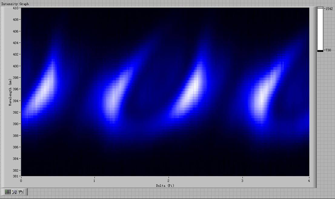 This image
resembles the ideal image that can be gotten using MIIPS Both were taken of a
δ of 4pi.
This image
resembles the ideal image that can be gotten using MIIPS Both were taken of a
δ of 4pi.
 <--
Courtesy of my graduate students.
<--
Courtesy of my graduate students.
Week 6: This week was a little slow in terms of research. Mainly I continued my task of learning programming. On Wednesday, we were working in the KLS, adjusting the optics of our system again. This time, the A/C was off so the room was unusually warm, 72°F, which affected our alignment. Unfortunately while we were making modifications, the power went off completely leaving us literally in the dark halting research for that day. Friday we were able to return to lab and obtained a few samples.
The last full week in Kansas began with more programming and discussion on acquired data. We do not have any scheduled beam time this week, but will hopefully get in on the weekend and the rest of next week. Until then we are analyzing the data we currently have.
|
|
|
|
|
|
|
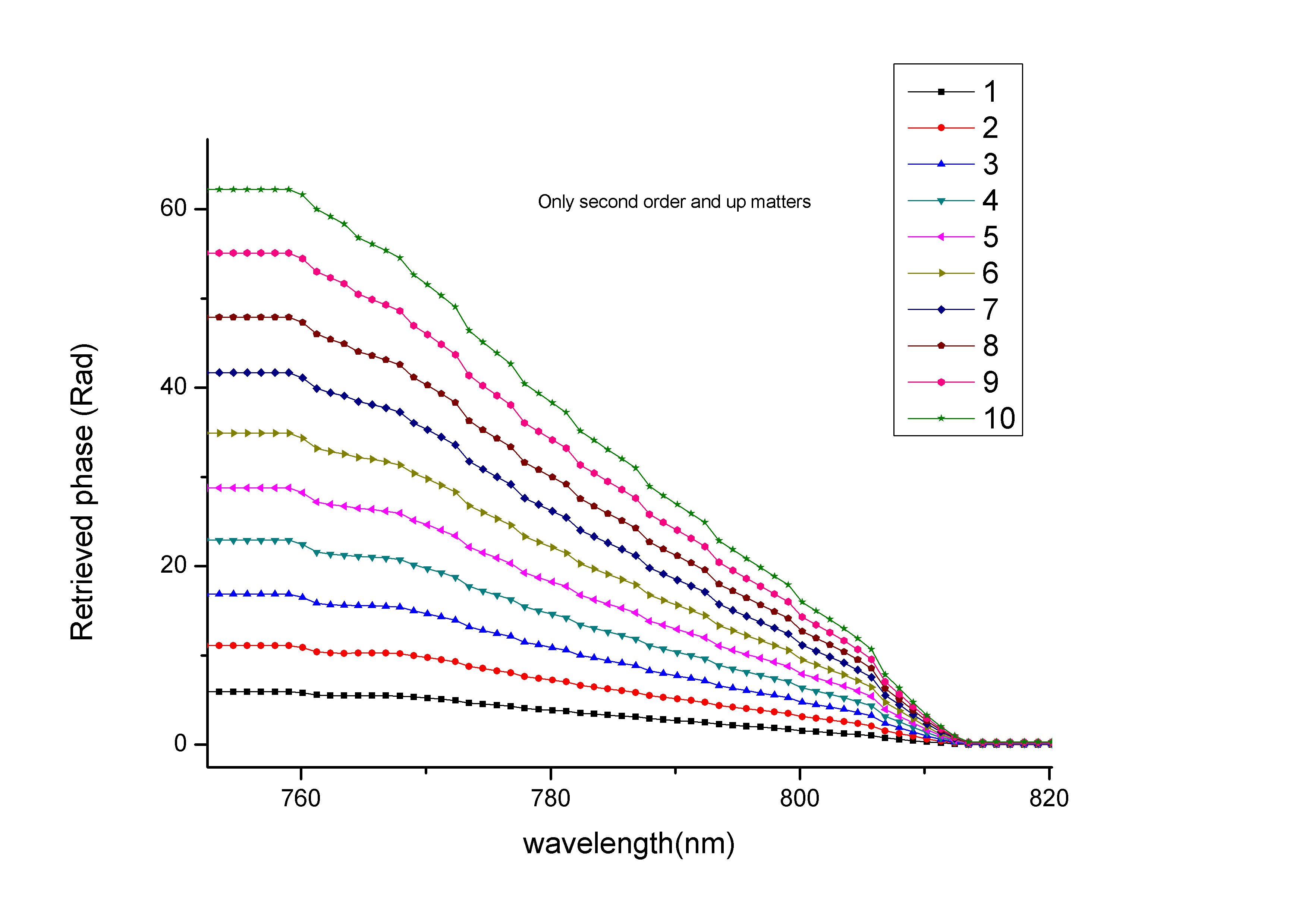
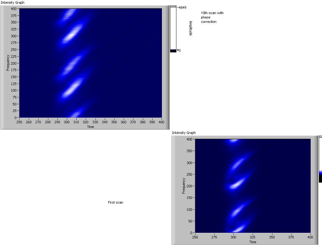
Week 8: Suddenly it all works. We had our program up and running, we had available beam time and we got some results
 First scan with new parameters
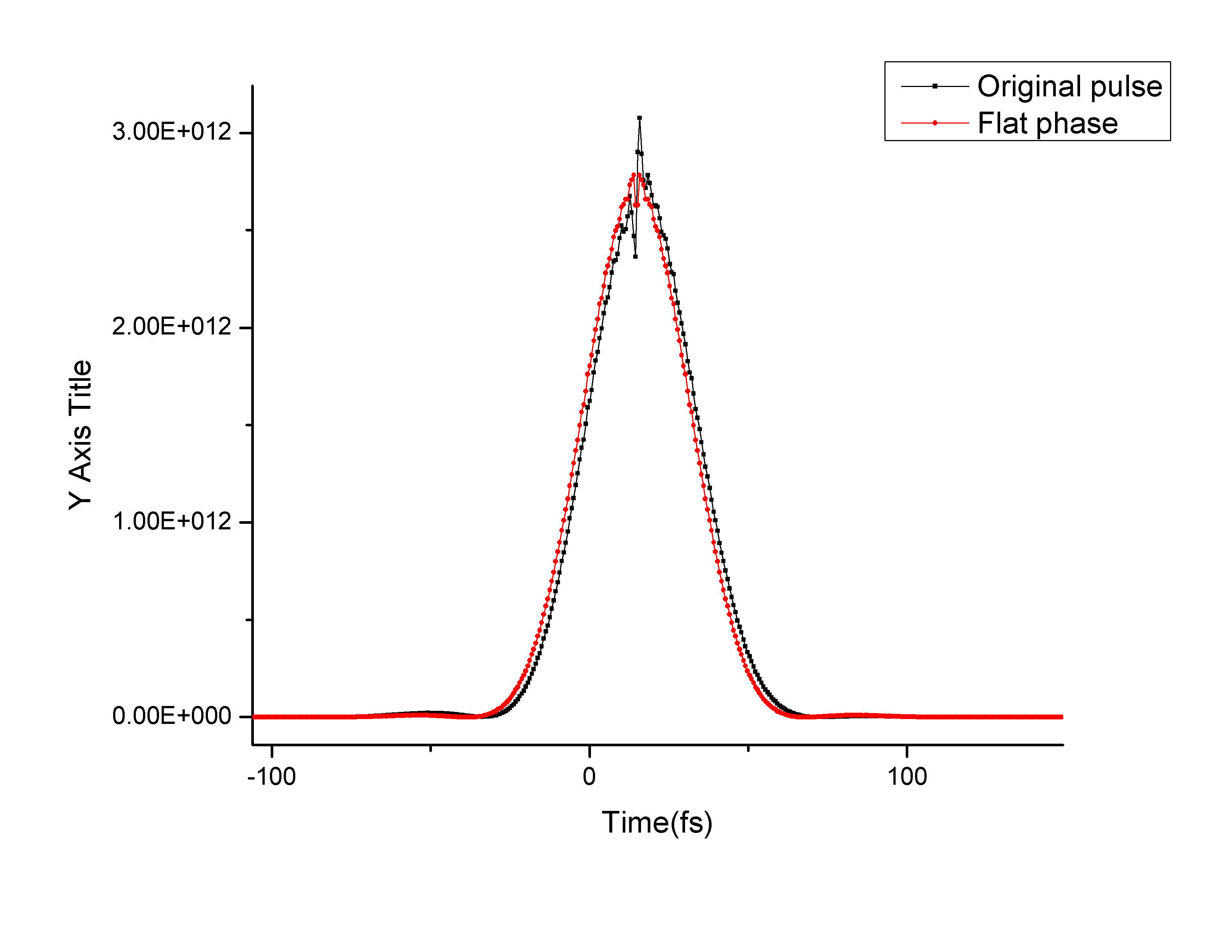
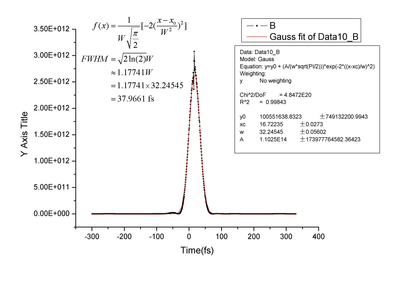
 Final scan with new parameters
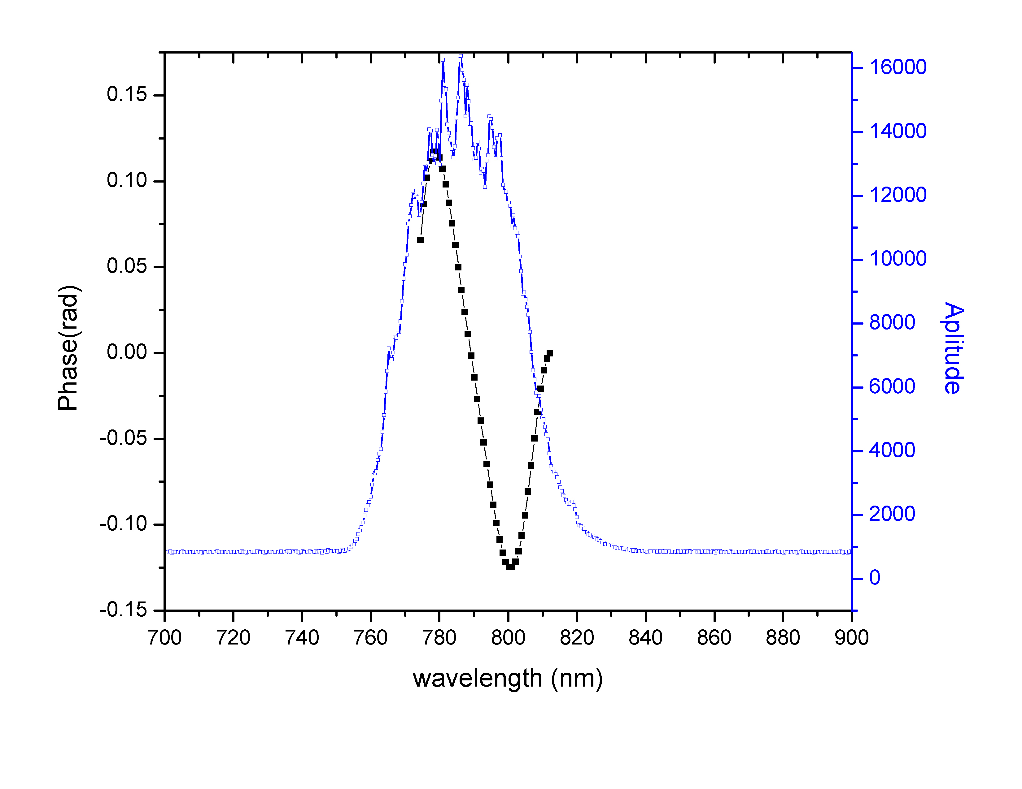
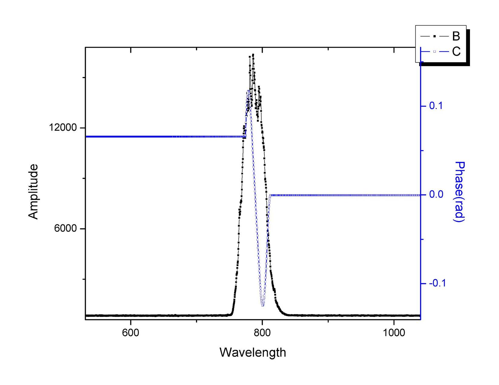
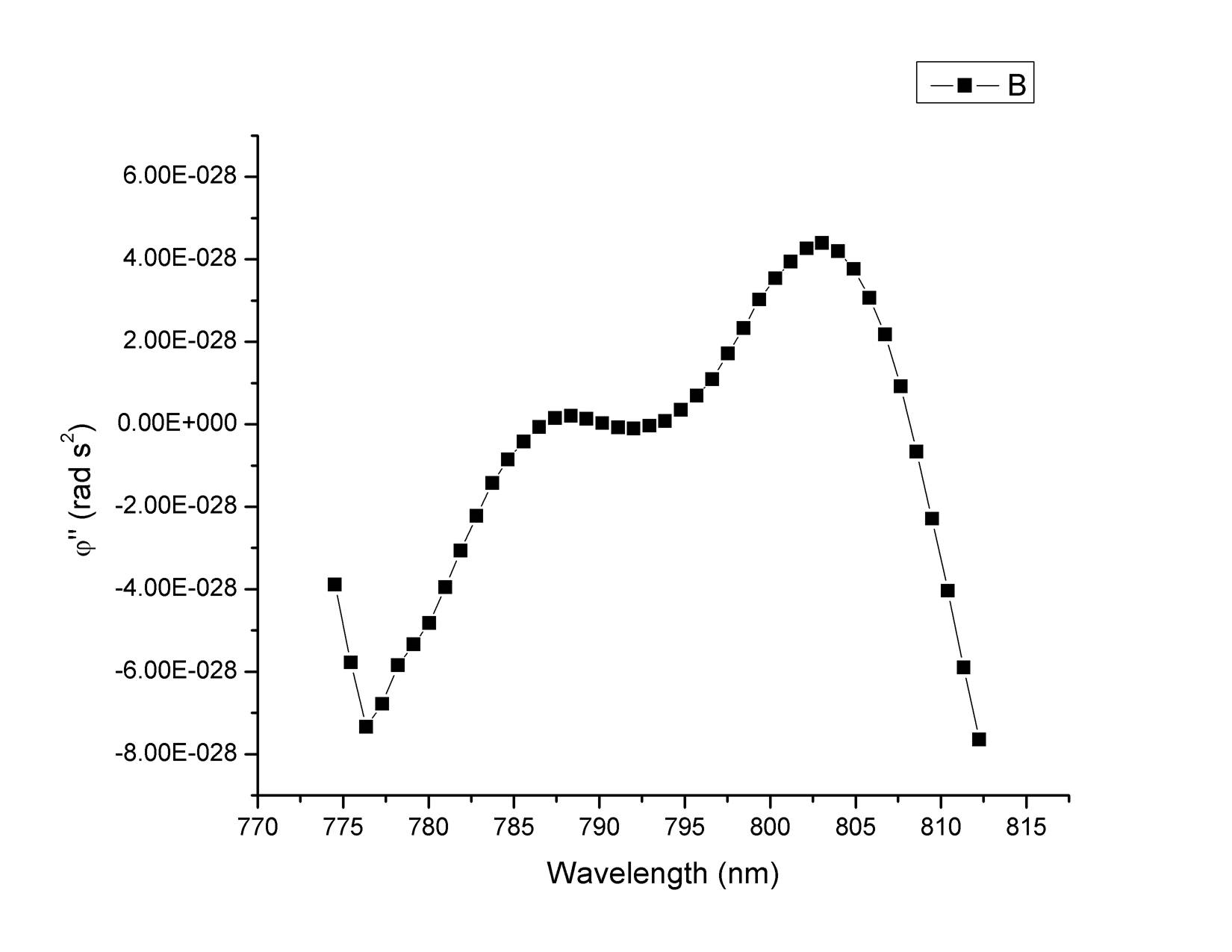
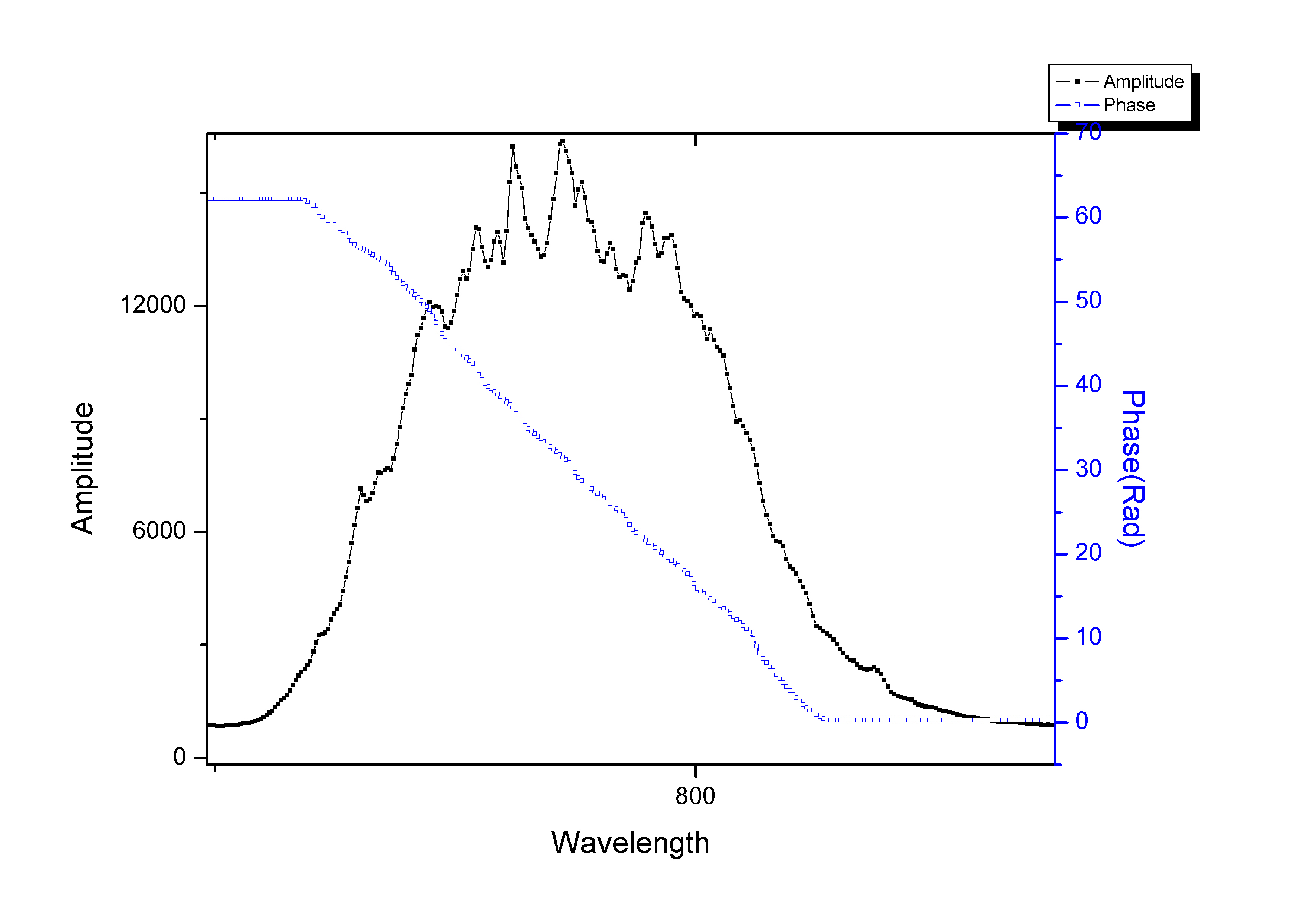 New spectrum and retrieved phase with current parameters
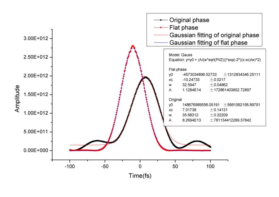
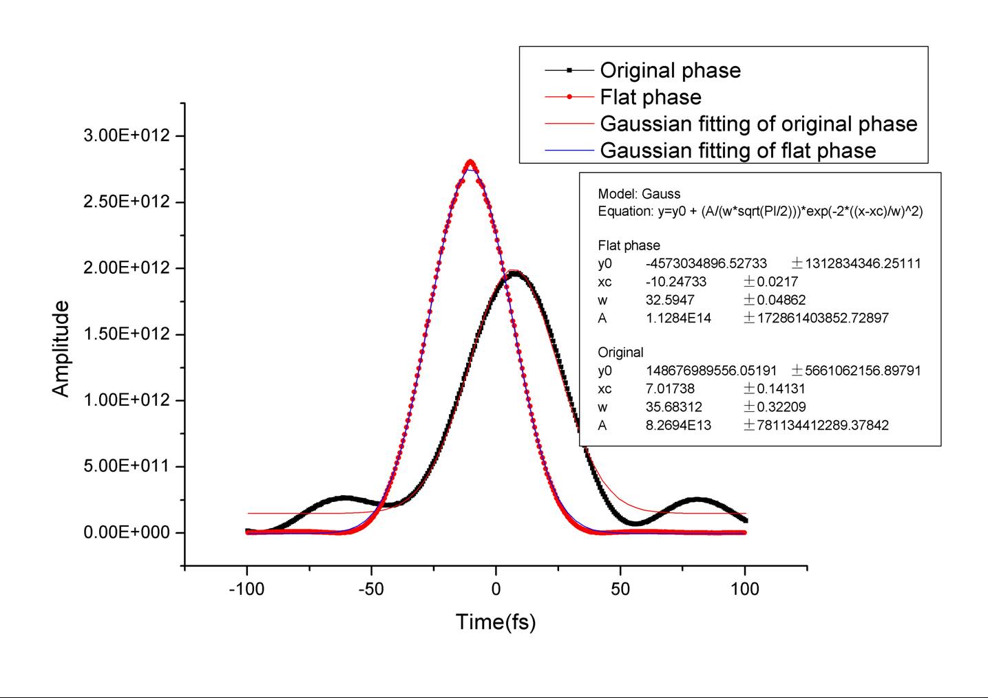
 ~ about 38 fs.
The above results are the conclusion of my summer of research at KSU REU 2007. I have greatly enjoyed this opportunity to learn and research here. For a final report on my activities this summer check out the Final Results PowerPoint or PDF file on my home page.