2/10/04clc
Electron Charge/Mass Ratio, Bainbridge Apparatus
In this experiment you will use a uniform magnetic field, generated by a set of iron-free Helmholtz coils, to deflect a beam of electrons of known energy in a circular orbit. The radius of the orbit provides a measure of e/m for the electron. A thorough description is given in the Welch manual, although some details of your experiment are slightly different (including some aspects of the circuits and power supplies) from those given there. Please use MKS units in your data and writeup.
Check and recheck your wiring before turning on any power. Do not exceed recommended filament current. The tube is expensive. Since some voltmeters and ammeters produce appreciable magnetic fields nearby, you may want to keep them as far from the tube as possible. Your apparatus list includes:
- e/m tube with Helmholtz coil
- Filament 2.5 ohm rheostats
- Three digital multimeters
- 1 Electro Products Filament supply.
- 1 Hewlett Packard 6274B regulated power supply for coils.
- Dressen-Barnes Regulated power supply for accelerating potential. Not that this supply is capable of delivering much more voltage than is necessary for this experiment.. Use the 0-300 + output. Be Careful!
USE THE FOLLOWING CIRCUIT DIAGRAM
Apparatus:
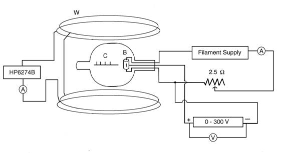
W = Circular coils
G = Glass bulb with air removed, containing mercury vapor
B = Hollow carbon cylinder
C= Cathode
K = Markers
The heated filament, which is inside B gives off electrons which are attracted to C which is +. Some of these electrons come thru a slit in cylinder and form a visible beam by ionizing the mercury vapor in the bulb. When a current flows thru coils W, the magnetic field produced causes the electron beam to be bent into a circular path.
Analysis: The energy of the electrons is determined by the potential difference V between filament (where? Watch out for the voltage drop across the filament) and carbon cylinder. The electrons move in a (uniform) magnetic field B directed perpendicular to the electron velocity. They follow F=ma , where F is given by e(v x B). The resulting motion is a circle of diameter D. Combining these equations results in
![]()
B = Magnetic field
V = Voltage between filament and cylinder
D = Diameter of electron path
e = Charge on electron
Derive above equation. Be sure to include proof in report.
B can be obtained from equation 
This is the field at the center of a Helmholtz coil.
B = Magnetic field
N = Number of turns in each coil = 72
I = Current in coils
A = Radius of coil = 0.33 m.
PROCEDURE: Connect apparatus as shown in diagram. Be sure to use the correct supply as a wrong connection could burn out tube. BE SURE NOT TO ALLOW MORE THAN 3.8 A TO FLOW THROUGH THE FILAMENT.
Allow ten minutes for tube to warm up. It is a good idea to also put an ammeter in series with the return path from the 300 V power supply to measure the electron emission current. You should measure around 2 mA. It will probably take about 3.7 A in the filament to get this much emission current from the tube. Connect coils to their power supply and note that electron beam is bent in circular path. Be sure that direction of current is such that beam is bent towards markers K. It may be necessary to darken room to see beam.
Correction for earth’s magnetic field:
To correct
for this effect set apparatus in North-South direction as indicated by compass. Also incline apparatus at an angle with
horizontal so that axis of coils forms an angle with the horizontal equal to
the angle of dip of the earth’s magnetic field (about 60 deg at
To find correction for earth’s field, find the current thru the coils required to produce a straight beam of electrons. Test with straight edge. Made several trials. Record all readings. Take the average. Should this value of current be added or subtracted from ammeter reading to correct for effect of earth field?
Set V at about 50 volts and adjust current thru coil so that the sharp outer edge of the beam is even with the outer edge of the farthest marker. (If beam is twisted turn tube about its axis to adjust.) Make several trials, record all readings. Calculate average. Repeat for each marker. Repeat with V at about 100 volts.
Marker number (Distance from filament to markers) :

Correct readings for effect of earth’s field.
Include corrected and uncorrected current values in your report.
Calculate B from equation given for each case.
Calculate charge/mass of electron for each case.
Find average value.
Look up accepted value and record.
Calculate % error.
THE FOLLOWING INFORMATION IS OLD ; USE IT ONLY IF YOU NEED FURTHER READING, AND DO NOT TRY TO USE THE CIRCUIT DIAGRAM GIVEN BELOW.
Sargent-Welch
Instructions
Instructions for
Use of No. 0623B e/m Apparatus
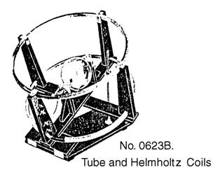
Description. Cat. No. 0623B e/m Apparatus consists of a No. 0623 e/m Vacuum Tube and a No. 0623a Helmholtz Coil Assembly.
The e/m Vacuum Tube has been designed for determining the ratio of charge to mass of an electron. It may also be used to demonstrate the curving of a beam of charged particles as they pass through a magnetic field, and as an aid in explaining the principle of the mass spectrometer. The Helmholtz Coils have been designed large and rigid to provide the uniform magnetic field required in the operation of the tube. The axis of the coils may be inclined to the dip angle for quantitative measurements and to a horizontal position for classroom demonstrations.
The tube is essentially the same as one descried by K.T. Bainbridge (American Physics Teacher 6, 35, 1938) who states that “Historically the method is of great interest as, in principle, it is the same as that described by A. Schuster in 1890 (Proc. Roy. Soc. 47, 526, 1890) and used by W. Kaufman in 1897 (Wied. Ann. 61, 544, 1897).” The present apparatus is based upon an improved version built and extensively tested by Professor Ralph P. Winch, Williams College, and incorporates various additional improvements developed in our own laboratory.
The beam of electrons in the tube is produced by an electron gun composed of a straight filament surrounded by a coaxial anode containing a single axial slit. See Fig. 1a and 1b for schematic diagrams of the tube. Electrons emitted from the heated filament F are accelerated by the potential difference applied between F and the anode C. Some of the electrons come out as a narrow beam through the slit S in the side of C. When electrons of sufficiently high kinetic energy (10.4 electron volts or more) collide with mercury atoms, mercury vapor being present in the tube, a fraction of the atoms will be ionized. On recombination of these ions with stray electrons the mercury-arc spectrum is emitted with its characteristic blue color. Since recombination with emission of light occurs very near the point where ionization took place, the path of the beam of electrons is visible as the electrons travel through the mercury vapor.
The magnetic field of the Helmholtz Coils causes the stream of electrons to move in a circular path the radius of which decreases as the magnetic field increases. By proper control of the magnetic field the sharp outer edge of the beam can be made to coincide with any one of five bars spaced at known distances from the filament.
Each coil of the pair of Helmholtz Coils has 72 turns of copper wire with a resistance of approximately one ohm. The approximate mean radius of the coil is 33 centimeters. The coils are supported in a frame which can be adjusted with reference to the dip angle so that their magnetic field will be parallel to the earth’s magnetic field but oppositely directed. A graduated scale indicates the angle of tilt. A safety device prevents the coils from accidentally dropping back to the horizontal. Wooden scats with retaining straps cradle the tube in a central plane midway between the two coils.
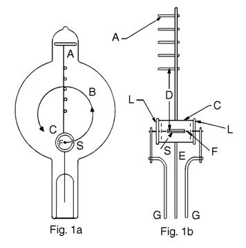
Figure 1a is a sectional view of the tube and filament assembly. Figure 1b is a detailed section of the filament assembly at right angles to Fig. 1a.
A: Five cross bars attached to staff wire.
B: Typical path of beam of electrons.
C: Cylindrical anode.
D: Distance from filament to far side of each of the cross bars.
E: Lead wire and support for anode.
F: Filament.
G: Lead wires and supports for filament.
L: Insulating plugs.
S: Slit in cylindrical anode.
Theory. When a charged particle such as an electron moves in a magnetic field in a direction at right angles to the field it is acted on by a force, the value of which is given by
![]() (1)
(1)
where B is the magnetic-flux density in webers/meter2, e is the charge on the electron in coulombs, and v is the velocity of the electron in meters/sec. This force causes the particle to move in a circle in a plane perpendicular to the magnetic field. The radius of the circle is such that the required centripetal force is furnished by the force exerted on the particle by the magnetic field. Therefore
![]() (2)
(2)
where m is the mass of electron in kilograms, and r is the radius of circle in meters, i.e. ½D. If the velocity of the electron is due to its being accelerated through a potential difference V, it has, due to its velocity, a kinetic energy of
![]() (3)
(3)
where V is the accelerating potential in volts. Substituting the value of v from Eq. (3) into Eq. (2)
![]() (4)
(4)
Thus when the accelerating potential, the flux density of the magnetic field, and the radius of the circular path described by the electron beam are known, the value of e/m can be computed, and is given in coulombs/kg by Eq. (4) if V is in volts, B is in webers/m2, and r is in meters. Note, Eq. (4) will give e/m in the electromagnetic units of abcoulombs/gm if V is in abvolts, B is in gauss, and r is in cm.
The magnetic field which causes the electron beam to move in a circular path has the magnetic-flux density B (in webers/m2) which, in terms of current through the Helmholtz Coils and certain constants of the coil, is
![]() (5)
(5)
where N is the number of turns of wire on each coil,
I is the current through coils in amperes,
a is the mean radius of coil in meters,
![]() is
the permeability of empty space, which is
is
the permeability of empty space, which is
![]() weber/ampere meter.
weber/ampere meter.
Substituting Eq. (5) in Eq. (4) gives

 (6)
(6)
Note. See Supplementary Comments at the end of these instructions for Eq. (5) and (6) expressed in the electromagnetic system of units.
Equation 6 is the working equation for this apparatus. The quantity within parentheses is a constant for any given pair of Helmholtz Coils. The value of r, the radius of the electron beam, can be varied by changing either the accelerating potential or the Helmholtz-field current. For any given set of values, the value of e/m can be computed.
___________
*Ralph P. Winch, Electricity and Magnetism. Prentice-Hall, Inc., 1955, pp. 504-506.
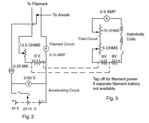
Accessory Apparatus. The following apparatus will be needed to perform this experiment. Most of it, or the equivalent, will normally be already available. See circuit diagrams, Fig. 2 and Fig. 3.
Filament Circuit
No. 3031J Ammeter, 10A, D.C. 2%
No. 2751 – 06 Rheostat, Slide-Wire, 2.5 ohms, 13A
No. 2606W Power Supply, 0 – 15V, 5A D.C.
or No. 2307B Storage Battery, 6 volts, 107 ampere - hours
Accelerating Circuit
No. 3034P Milliammeter, 25mA D.C. 2%
No. 3018W Voltmeter, Type A, 30/15/3V D.C., 0.5%
No. 0620L Power Supply, 0-300V, 30mA D.C.
Field Circuit
No. 3000B Ammeter, Type A, 5A D.C., 0.5%
No. 2751 – 10 Rheostat, Slide-Wire, 5 ohms, 9.2A
No. 2751 – 35 Rheostat, Slide-Wire, 170 ohms, 1.6A
No. 2606W Power Supply, 0-15V, 5A D.C.
or No. 2307F Storage Battery, 12 volts, 60 ampere-hours
In addition, three sp/st knife-type switches such as No. 2990 are desirable. A magnetic dip needle such as Cat. No. 1875 will also be needed. Cat. No. 2748H Variable Carbon Rheostat is a good substitute for the 2.5-ohm and the 5-ohm slide-wire rheostats.
Setting Up the Apparatus. The Helmholtz Coil Assembly is partially “knocked down” for shipment. The parts removed are a long slotted and graduated strip attached to a flush plate, a right-angle casting with clamp, and a rubber bumper. The rubber bumper is to be located on the base board so it will be beneath the bumper on the hinged board. The flush plate is attached to the base board by the three screws that are provided. The right-angle casting with clamp is attached to the under side of the hinged board. This is to be used as a friction brake and should be so regulated that if the clamp screw is loosened while the e/m tube is mounted, the hinged board will settle slowly without shock.
The room should be fairly well darkened for demonstrating and making measurements with the e/m tube. If a table about 16 inches high is available, its use will permit the observer to lean over the Helmholtz Coils and view the beam perpendicular to its plane. If the coils are placed on a table of normal height the observer will have to stand on a chair to see the beam from the proper direction. The wooden box used for shipping the coils is of the right height to make a good support on which to place the apparatus. Its use is suggested if a table or other support is not available.
Place the tube in its support in the center of the frame. The end of the tube from which the leads extend should be adjacent to that part of the frame on which connectors are mounted. Secure the tube in place with the straps.
Orient the Helmholtz Coils so that the e/m tube will have its long axis in a magnetic north-south direction, as determined by a compass. Measure the magnetic inclination at this location with a good dip needle. Tip the coils up until the plane of the coils makes an angle with the horizontal equal to the complement of the dip angle. The axis of the coils should now be parallel to the earth’s magnetic field.
Make electrical connections to the tube as shown in Fig. 2. Use a power supply with variable D.C. output or a 6-volt storage battery to supply the filament current. See Supplementary Comments for suggestions relative to the use of an A.C. filament supply. Use a slide-wire rheostat of 2.5 ohms resistance to control the filament current. An ammeter of 5- or 10-ampere range and 2% accuracy is satisfactory for measuring this current. Use a high-resistance voltmeter of 1000 ohms per volt, or higher, to measure the accelerating voltage accurately. A voltmeter of 0.5% accuracy, or better, is essential here.
Make electrical connections to the Helmholtz Coils as shown in Fig. 3. The ammeter used in this circuit for measuring the field current should have 0.5% accuracy or better. The two coils are connected in series and the current sent through them in such a direction that their magnetic field is oppositely directed to the earth’s field. Knife-type switches in each of the three circuits, as shown, will be helpful. Tape any bare connections at the tube to avoid short circuits.
NOTE:
Operation. The filament of the e/m tube has the proper electron emission when carrying 2.5 to 4.5 amperes. Exceeding 4.5 amperes will materially shorten the tube’s life. Good results can be obtained using an accelerating voltage of 22½ to 45 volts. An electron emission current of 5 to 10 mA gives a visible beam. For maximum filament life operate the tube with the minimum filament current necessary for proper electron emission. It is helpful and good practice to apply about 25 volts accelerating potential to the anode before heating the filament. Always start with a low filament current and carefully increase it until the proper electron emission is obtained. Since the electron beam appears suddenly it is advisable to increase the filament current slowly to avoid overheating and possibly burning out the filament.
Apply 20 to 30 volts accelerating potential to the tube. With maximum resistance in the filament circuit, close the switch in this circuit. Gradually decrease this resistance until the milliammeter indicates 5 to 10 mA and the electron beam strikes the tube wall. Rotate the tube in its cradle until the electron beam is horizontal and the bars extend upward from the staff wire. Note that the electron beam is deflected slightly toward the base of the tube by the earth’s magnetic field.
Now send a small current through the Helmholtz Coils. If the magnetic field of the coils straightens the beam or curves it in the opposite direction, the coils are correctly connected. If this field increases the deflection toward the base, the current is flowing through the coils in the wrong direction and the connections must be reversed. If no effect is observed on the beam, the field due to one coil is opposing that of the other and connections to one coil must be reversed. Make any necessary changes and increase the field current sufficiently to cause the beam to describe a circular path without striking the wall of the tube. The apparatus should now be ready for obtaining the necessary data to compute the value of e/m.
Data and Results. In the manufacture of the e/m tubes the crossbars have been attached to the staff wire and this assembly attached to the filament assembly in precise fixtures which accurately control the distances between the several crossbars and the filament. Distances given are to the far side of the crossbar.
Crossbar Number Distance to Filament (D)
1 0.065 meter
2 .078 meter
3 .090 meter
4 .103 meter
5 .115 meter
These distances are the diameters of the several circles which the electron beam will be caused to describe. Following the prescribed procedure, heat the filament until the electron beam is visible. Allow a few minutes for warm-up and temperature equilibrium.
Following the prescribed procedure, heat the filament until the electron beam is visible. Allow a few minutes for warm-up and temperature equilibrium.
Close the circuit comprising the Helmholtz Coils and adjust the value of the current until the electron beam is straight. One method is to adjust the beam until it is aligned with a straightedge held as close to the tube as possible. Another method is as follows. Increase the current through the coils until the beam shows a slight curvature as compared with the straightedge and record the value of the current. Then decrease the current until the beam shows an equal curvature in the opposite direction and record the current. The average of these values will be the value of the current required to straighten the beam. This adjustment should be made carefully and accurately. When the beam is straight the magnetic field of the coils just equals the earth’s magnetic field. Record the value of this current as I1 in a table similar to Table 1. The value of I1 is dependent only on the accelerating voltage, V, and the earth’s magnetic field. It is constant unless V is changed; in which case I1 must be redetermined.
Table 1. Data and Results
|
Crossbar No. |
D |
R |
V |
I1 |
I2 |
I |
e/m |
|
|
|
|
|
|
|
|
|
|
|
|
|
|
|
|
|
|
|
|
|
|
|
|
|
|
|
|
|
|
|
|
|
|
|
|
|
|
|
|
|
|
|
|
|
Increase the field current until the electron beam describes a circle. Adjust its value until the sharp outside edge of the beam strikes the outside edge of a crossbar. Record this value as I2 in the table. The outside edge of the beam is used because it is determined by the electrons with the greatest velocity. The electrons leaving the negative end of the filament fall through the greatest potential difference between filament and anode, and have the greatest velocity. It is this potential difference which the voltmeter measures.
Determine and record the field current required to cause the electron beam to strike each of the other bars. Subtract I1 from each value of I2 and record it as I. This is the value of the current to be used in Eq. (6) for computing e/m. Compute e/m for each value of I.
Repeat the above and determine e/m using a different value of accelerating voltage. Compare the results with the accepted value of e/m, which is 1.76 x 10¹¹ coulomb/kg.
Supplementary Comments
1. By subtracting the field current just necessary to overcome the earth’s field from the total field current required to curve the beam into a given circular path, the effect of the earth’s field on the determination of e/m is eliminated and there is no need to know or otherwise determine the earth’s magnetic field. However, if desired, the value of the earth’s magnetic field may be computed using the value of I1 in Eq. (5). Another method of measuring the earth’s field and correcting for this in the evaluation of e/m is given in the reference listed at the end of this section.1
2. The tube can be used quite effectively as a demonstration in a well-darkened lecture room. For the most effective demonstration the whole unit should be tipped until the axis of the coils is nearly horizontal. In this position the tube and the beam of electrons are most easily seen by the class.
3. If the magnetic field of the Helmholtz Coils is increased sufficiently to cause the electron beam to describe a circle of small radius, then by rotating the tube slightly the beam will spiral either upward or downward. Reversing the filament current will reverse the direction of the spiral, the spiraling of the beam being caused by the magnetic effect of the filament current. A reversing switch in the filament circuit is helpful during this demonstration.
4. The action of this e/m tube and Helmholtz Coils can be used in explaining the principle of a mass spectrometer. A consideration of Eq. (6) shows that for charged particles carrying the same charge but differing in mass the radius of the circular path into which they are caused to move by the magnetic field differs for particles of different masses. Knowing the value of the charge and measuring the radius of the circular path, the mass of particles can be determined. This is essentially what is done in a mass spectrometer.
5. In the electromagnetic system of units, Eq. (5) is
![]()
and Eq. (6) becomes

where a and r are in cm, V is in abvolts, B is in gauss, and I is in abamperes. In this system the accepted value of e/m is 1.76 x 10⁷ abcoulombs/gram.
6. Users have reported the satisfactory use of alternating current for heating the filament.2 By using a step-down transformer with a 6-volt center-tap secondary the accelerating circuit can be connected to the center of the filament thereby reducing the uncertainty of the value of the accelerating voltage. If this is done, it is suggested that the filament current be controlled by a rheostat in the primary of the transformer or by use of a variable transformer to control the step-down transformer. The use of alternating current in the filament also effectively eliminates the magnetic field of the filament current.
References describing other power supplies are listed below.3,4
- D.S. Ainslie, Am. J. Phys. 26,
496 (1958).
- M. Iona, H.C. Westdal, and P.R. Williamson, Am. J. Phys. 35, 157 (1967).
- R.W. Christy and W.P. Davis, Jr., Am. J. Phys. 28, 815 (1960).
- G.W. Ficken, Jr., Am. J. Phys. 35,
968 (1967).
Instructions supplied with Sargent-Welch apparatus are intended primarily as an aid to the teacher in preparing the apparatus for use and in becoming acquainted with its operation. The experimental procedure suggested is not necessarily the most appropriate for all students. It is assumed that each teacher will develop a procedure best suited to his students. Information regarding any applications of the apparatus which have proven especially interesting and instructive will be gratefully received by Sargent-Welch Scientific Company, 7300 N. Linder Avenue, Skokie, Illinois 60076.
Revised J83170HH.