First Week:
During my first week working in LUMOS lab, I learned how to use a commercial device to fusion splice SMF 28e Fibers. This was an important step in my accommodation with handling fibers. In order to splice two fibers and obtain a minimal loss, one has to prepare them first. This includes:
-striping the fibers
-cleaning them with optical cleaning tissue
-cleaving the fibers and placing them into the splicer.
It is important not to touch anything with the fibers once they are cleaned and cleaved in order to avoid any contact with dust in the air which might minimize the signal transmission once the splice is done. If the fibers are too dirty, sometimes the splice is impossible to be accomplished. During my first week I also learned how to turn on the CO2 laser, and how to use it. After I knew how to turn on the laser, I had to know where the beam was, since it is an infrared laser of wavelength 10,600nm. The easiest way of knowing where the CO2 laser is at all times, is to align it with a HeNe laser, which has a visible wavelength of 365nm (red light).
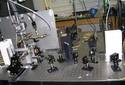
In the picture above, "m" followed by a number stands for the different mirror we use in our setup to direct the laser beams. The combiner is a piece of ZnSeO3 which lets the CO2 beam pass through it, but reflects the HeNe light, therefore superposing them. The mirrors m2 and m3 are used to align the 2 beams at the check points between m1 and the combiner, and m5 and the lens. At these check points, I put a metal stand with black, chemical paper attached to it. I use that setup to burn a hole with the CO2 laser, and see if it is at the same place as the HeNe laser. I also made sure that they pass through the center of the ZnSe lens and roughly through the center of the combiner as well.
Second Week:
One of the first things I did during my second week was to measure the input power through the fiber to be spliced to another SM fiber. The average power found at that point was about 2.257dBm. I had some difficulties with that step since the position of the fibers during the measurements influenced the power reading. I attempted my first splice with the CO2 laser, and did not get a splice. To find a full description of what the preparations for a splice are, visit the "Research Steps" link on the Home page. During this second week, I found out that the magnets in the clamps were not tightened the right amount, therefore I could not apply the stuffing stroke since the fibers were slipping. Later in my research I found out that the magnets were not the only problem, but that is another matter of discussion, later on. So keep on reading.
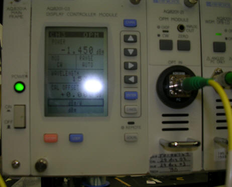 This is an illustration of the aligned fibers, when the power passing through is
-1.450dBm.
This is an illustration of the aligned fibers, when the power passing through is
-1.450dBm.
Third Week:
This week was one of changes... I replaced the micrometers on the jig since they were not very precise and were very hard to move. Up to this point in time, it took me about 2-3 hours to align the two fibers before being able to apply the stuffing stroke. After replacing the micrometers, the first splicing attempt was a success (if I can call it that). By success I mean that the fibers staid together. Before the stuffing stroke, the power through the fibers was -2.150dBm, and the power after the splice was -4.526dBm. For the rest of the week, the splices have not improved, actually I was not able to get any more splices after which the fibers would still be attached. At this point in time, aligning the fibers before the stuffing stroke was also taking me a very long time, about 2 to 3 hours.
Fourth Week:
Every week is a week of progress of some type, although sometimes progress in research is described by finding more problems with the system and ways of fixing it, rather than getting better results. This week I managed to align the fibers in only 20-25 minutes, as opposed to 2-3 hours. During one of the first splice attempts this week, I align the fibers until the power through them was +1.509dBm before the stuffing stroke, and -0.540dBm after the splice. The splices now are pre-heated for 20 sec. at 0.4 V, and heated at 1V for another minute or more. Although during the heating and splicing of the fibers the power behaves as expected (see final report), when I opened the clamps, the splice (if it occurred) broke. When I checked the clamps to see if they were holding the fibers well, I observed that the fibers were slipping, depending on the amount of coating left on the clamped part of the fibers. As long as there was any coating clamped, the fibers were not slipping. The slipping of the fibers was influencing the strength of the stuffing stroke.
Fifth Week (Happy 4th of July!):
The power input is oscillating, which means that each time I make a splice, I need to check the power input right after the splice in order to know what the loss is through the splice. Besides the power instability, the lasers were misaligned AGAIN! I came to the conclusion that the lasers were not aligned with the fibers and each other since when I heated the fibers there was practically no change in power compared to the after stuffing stroke power reading. After the alignment problem was solved, the next splice behaved well from the power reading perspective, but as last week, as soon as the clamps were opened, the splice did not hold. I observed this time that the fiber was stuck to the rubber on the bottom of the opened clamp, which made me think that glass and rubber stick together sometimes when there is enough pressure for a certain amount of time. The solution I came up with was to tape a little piece of fiber cleaning tissue to the bottom of the clamp, such that it would cover the rubber. Nothing is better than some improvisation ;-).
 Clamp with tissue taped on.
Sixth Week:
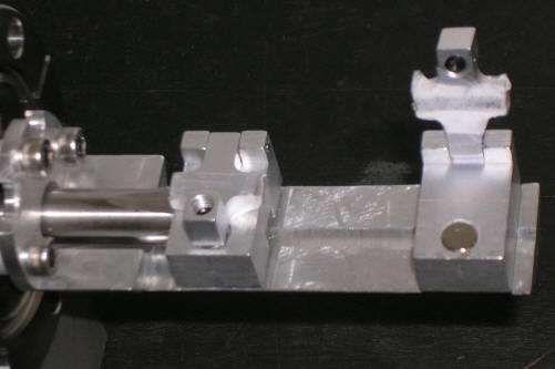
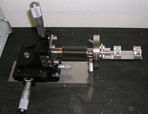
After the sticky problem was solved, the next few splices which did not break had a very large break radius, approaching infinity, which means that the splice was not very strong. These splices were pre-heated at 0.4V for 20 sec, and heated at 1.5V for about a minute, or until the power started decreasing again, and I would block the CO2 laser with a fire brick. The best question one could ask while doing research is: "What's the next problem I get to have fun with?" Although I got rid of the sticky problem, as its name shall remain, I also had to take into consideration the fiber length problem. By the end of this week I got rid of the stable clamp on the jig and used a separate clamp in order to be able to control the length of the fibers clamped down. Maybe a picture will explain this better:
From previous work done on this project, we found out that the best length for each fiber in the clamp is 1 cm. Therefore the optimal distance between the two clamps should be 2.5-3 cm, in order to allow space for alignment. After I set the system at the new parameters, I also increased the voltage through the CO2 laser. The new preheating values were set at 0.65V for 20 seconds, and the heating at 3.00 V for about 1 minute, or until the power went down. The first splice with these setups behaved as follows: The power after my alignment was +1.343dBm, and after the splice it was +2.097dBm. This was the first splice with no loss, done with the CO2 laser.
Seventh Week:
The jig suffered its first change this summer. Now it allows 2 cm of fiber to be clamped down, and therefore allows more perfect splices to be obtained. The "perfection" of the power transmission from one fiber to the other also depends on the fiber curvature, and since the vacuum chamber is rather small, I have to use all the space available. This week I also had the first "perfect" splice inside the vacuum without any windows on, and in air.
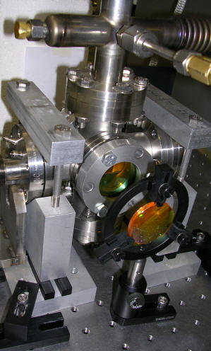 Vacuum chamber with the ZnSe windows on.
After I put the ZnSe windows in place, the next splice was not perfect. The power loss was about 0.615dB. The splice also happened in a shorter amount of time, which is due to the fact that the windows moved the focus of the laser closer to the fibers. Another problem discovered this week was the design of the jig. When I pumped out the air in the vacuum chamber with the jig in place, the adjustable clamp was sucked in by the pressure inside the vacuum chamber.
Eighth Week:
 Another week
of major design changes as you can see. I switched two of the micrometers around
in order to prevent the movement of the adjustable clamp inside the vacuum
chamber. When I started the summer, I was afraid of touching anything, and now I
am taking everything apart and putting it back together. One thing one has to
remember is: you cannot be afraid of breaking things, or else you'll never do
anything. During this week I encountered another problem... (is it even
surprising anymore?) The power reading is not very reliable due to making and
breaking of fiber connections throughout the circuit. Therefore I had to install
a beam splitter in order to avoid these connection breakings. This week was also
a week of preparation for my final presentation =(... It's almost over.
Another week
of major design changes as you can see. I switched two of the micrometers around
in order to prevent the movement of the adjustable clamp inside the vacuum
chamber. When I started the summer, I was afraid of touching anything, and now I
am taking everything apart and putting it back together. One thing one has to
remember is: you cannot be afraid of breaking things, or else you'll never do
anything. During this week I encountered another problem... (is it even
surprising anymore?) The power reading is not very reliable due to making and
breaking of fiber connections throughout the circuit. Therefore I had to install
a beam splitter in order to avoid these connection breakings. This week was also
a week of preparation for my final presentation =(... It's almost over.
![]()