2/11/06 clc
Electron Charge/Mass
Ratio, Hoag Apparatus
Here a modified
cathode-ray tube is used to measure e/m for the electron.A
beam of electrons is sent down the axis of the tube parallel to a known
magnetic field supplied by a solenoid.When the beam
is caused to begin its trajectory with some lateral motion, its lateral
trajectory will be a circle.Focus of the beam on the
tube face occurs when the time for completing the circular path is equal to
that for trip down the tubes axis, and the value of
magnetic field needed to obtain this condition provides a measure of e/m.
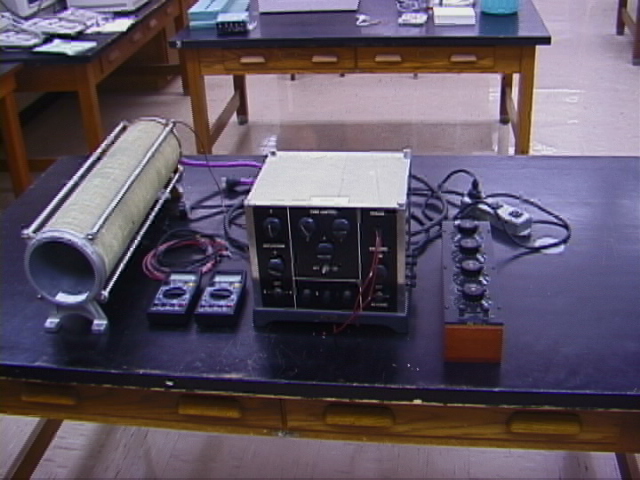
The apparatus includes:
·
e/m cathode-ray tube
·
Solenoid
·
Tube control circuit
·
2 digital multimeters
·
External resistance box (coarse solenoid current
control)
The accelerating and grid voltages
are generated in the grid control box.The solenoid current
supply, ~100 V D.C., will be provided to your table from a house D.C.
generator.
Please handle the tube with
care. Measurements of lx and ly
are difficult due to the opacity of the tube.Past
measurements have yielded ly=15.29 cm and
lx=13.21 cm from the back of plates to screen.
Q.Is the write-up correct in assuming that the entire
deflection takes place immediately when the electron enters the deflection region?How would you improve on
this assumption?Hint:The electrons follow a roughly
parabolic trajectory in the region of the deflection plates.Is
this effect a large one?
|
|
Tips: Be sure the ground cable is connected. Keep the
brightness (B) as low as possible.
|
|
WELCH
MANUAL
INSTRUCTIONS FOR THE USE OF
#627 HOAG E/M APPARATUS
Manufactured by
W.M. WELCH MANUFACTURING COMPANY
1515
Sedgwick St., Chicago, IL
THE PRINCIPLE OF
OPERATION
The
most important part of the apparatus is the special vacuum tube.This
is similar to the RCA-906 cathode ray oscillograph
tube except that it has been constructed entirely of non-magnetic materials.It may be used in place of a 906 tube in any
application.
As used in the
experiment to determine the ratio of charge to mass (e/m) of the electron, the
narrow beam of electrons produced in the gun of the tube passes between the
plates of a condenser and continues to a luminescent screen where it produces a
small spot of light.An alternating potential applied
to the condenser plates deflects the electron beam rapidly back and forth so
that a line of light appears on the screen.The tube
is also located in a uniform magnetic field in such a manner that the magnetic
lines of force are parallel to the axis of the tube.Under
these conditions the magnetic field does not effect the forward motion of the
electrons since the lines of force are in the same direction as the beam, but
it does act upon the perpendicular component of their motion (which was
produced by the electrostatic field of the condenser).From the elementary motor
rule, one may see the effect is to deflect the electrons into circles in planes
at right angles to the tube axis.The circles are
larger for the larger electrostatic deflecting potentials and are all
tangential to the axis.It can be shown that the time
for an electron to rotate at a slow speed in a small circle is the same as for
one to rotate rapidly in a large circle; all electrons rotate with the same
angular velocity.The result of the combined uniform
circular and uniform linear motions is such that the electrons follow helical
paths down the tube.
The strength of the
magnetic field is varied until the time for the electrons to make one
revolution is equal to the time for them to travel forward from the condenser
plates to the screen.Then all electrons will again be
on the axis and a spot of light will be derived and used to calculate the value
of e/m.
The
procedure is:first, to focus
the electrons on the screen, second, to apply the electrostatic field so as to
form a straight line on the screen, third to apply and increase the magnetic
field until the line has rotated and shrunk into a small spot of light, fourth,
to substitute in the equation for e/m.
MEASUREMENTS
ON THE SOLENOID
(1)Measure the length
L of the solenoid, in centimeters.This is the
distance between the ends of the turns of wire and does not include the end plates.See Figure 1.
(2)Measure the mean radius r of the
solenoid, in centimeters.To do so, measure the
outside diameter of the wires and also that of the supporting tube.Their sum, divided by 4, is the distance r form the
axis to the center of the windings, see Figure 1.Tan
 is
equal to r divided by L/2 and cos
is
equal to r divided by L/2 and cos
 may
be found directly in trigonometric tables.
may
be found directly in trigonometric tables.
(3)Record N, the
total number of turns of wire on the solenoid.
CONNECTIONS
(1)Arrange
the apparatus as in Figure 2 placing the solenoid in a location as free as possible
from magnetic objects and stray magnetic fields and at least one and one-half
feet from the Control Box and motors.The magnetic
fields of the transformers in the Control Box and of the permanent magnets in
the meters are thus avoided.
(2)Turn the Off and On switch of
the Control Box to the Off position and the Solenoid switch (lower right) to
its Off position.
(3)In the rear center of the
Control Box, plug in the tube cable and slide the tube in its holder into the
rear of the solenoid so that the white screen may be seen from the front.The center of the tube should be located at the
center of the solenoid as in Figure 1.The center of the tube is located
behind the screen by a distance equal to the sum of lx and ly divided by 4. This location of the tube may
be in error by a centimeter or two without seriously affecting the final result
since the magnetic field decreases but slowly along the axis, near the center,
of the solenoid (0.3% in 5 cm).
(4)Connect the ground wire provided
with the apparatus to the single binding post on the rear of the solenoid.If the metal tube of the solenoid is not grounded,
erratic operation of the spot of light will result due to electrostatic charges
on the glass walls of the vacuum tube.
(5)Connect wires from the pair of
binding posts on the solenoid to the right end terminals of the Control Box,
which are marked To Solenoid.Polarity is
unimportant, as a reversing switch has been provided on the box.
(6)Connect a 0-1000 d.c. millimeter of good quality to the left side terminals,
marked
 .This
serves to measure the current through the solenoid and should cover the range
from 0.1 to 0.9 amperes in steps of 0.01 amperes.Accurate
values of this current are very essential since they are squared in the final
equation and any error in their value will cause twice as large an error in the
computed value of e/m.
.This
serves to measure the current through the solenoid and should cover the range
from 0.1 to 0.9 amperes in steps of 0.01 amperes.Accurate
values of this current are very essential since they are squared in the final
equation and any error in their value will cause twice as large an error in the
computed value of e/m.
(7)Connect a 0-1500 d.c. high resistance voltmeter to the left side
binding posts marked
 .This
serves to measure the total voltage used in the acceleration of the electrons.A Weston d.c. 1000 ohms
per volt, model 489 meter, reading to 750 volts, has been used satisfactorily
in series with a multiplier of equal resistance, i.e., 750,000 ohms.The scale reading is then to be multiplied by two.The resistance unit used as a multiplier must be
capable of dissipating sufficient heat, say 10-25 watts, that it does not
overheat and change in value during use.Western
Electric lavites have been found satisfactory but
others of equal heat capacity may be used.Calibration
may be made, below 750 volts, by comparing readings with and without the
multiplier, to see that the added resistance decreases the readings to half value.Accuracy in the voltmeter readings is not as
important as in the ammeter readings.
.This
serves to measure the total voltage used in the acceleration of the electrons.A Weston d.c. 1000 ohms
per volt, model 489 meter, reading to 750 volts, has been used satisfactorily
in series with a multiplier of equal resistance, i.e., 750,000 ohms.The scale reading is then to be multiplied by two.The resistance unit used as a multiplier must be
capable of dissipating sufficient heat, say 10-25 watts, that it does not
overheat and change in value during use.Western
Electric lavites have been found satisfactory but
others of equal heat capacity may be used.Calibration
may be made, below 750 volts, by comparing readings with and without the
multiplier, to see that the added resistance decreases the readings to half value.Accuracy in the voltmeter readings is not as
important as in the ammeter readings.
(8)Plug in the 110 volts a.c.The lead wire may be found coming out of the rear of
the Control Box, near the tube cable plug.
(9)Connect the
100 d.c. to the binding posts on the right side of
the Control Box.The lowest voltage that can be used
is about 90 volts.If higher voltages alone is
available, such as 220 d.c., add a series resistor to
limit the current to 1 ampere.
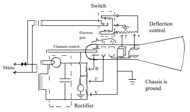
ADJUSTMENT
When the apparatus has been properly
connected, turn the main switch in the Tube Control section of the Control Box
to the On position.After about half a minute, a
green spot of light should be seen on the screen.If
none appears, turn the knobs B and F.As seen in
Figure 3, the knob B controls the negative potential of the grid G and hence
the number of electrons which can pass out of the gun; in other words, B
controls the Brightness of the spot on the screen.It
may also be seen in this figure that the knobs F and V control the positive
potentials on the two annodes A1 and A2.The
sharpness of focus of the electron beam is determined by the ratio of these two
potentials, so that F serves (for a fixed value of V) to determine the Focus of
the beam on the screen.A change in any of the B, F or
V values will alter the remaining values.
The theory used in
this method of determining e/m requires that the electrons travel in a parallel
beam through the condenser; they must not converge or diverge from the axis
until the electrostatic potential is applied to the plates.The
cross-over image of the cathode is about one-half millimeter in diameter.This, then must be the approximate size of the
spot on the screen.
Set the voltage at a fixed value,
say about 1200 volts, by turning the knob V.Now, vary
B and F so as to reduce the size of the spot until it is a millimeter or less
in diameter and as nearly circular as possible (no tails).The spot will not be
intensely brilliant but may be seen without darkening the room.This
adjustment is exceedingly important, for if the spot is too large, the
electrons will start diverging from the axis somewhere in the gun and the values
of lx and ly used in the
computations will be smaller than the true values and e/m will come out too large.Conversely, if the spot is too small, e/m values will
be too small.Since the exact conditions, which
produce a parallel beam can only be stated in terms of the size of the spot on
the screen, the student should try various sizes from one millimeter down to
the smallest which is visible in the following.
THE EXPERIMENT
(1)With
a circular spot of about one-half millimeter diameter, turn the Deflection
switch to X and vary the X knob until the faint line, which appears on the
screen is of maximum length.It will be shorter at the
higher voltages.The exact length is not of great
importance.
(2)Now turn the Solenoid switch
to, say the left side and increase the solenoid current, first with the coarse
and later with the fine adjustment until the line has been reduced to a small point.This is an exceedingly sharp adjustment and hence can
be made with considerable accuracy.When the line has
been reduced to a small point the electrons have executed one helical
revolution and the equation for e/m (to be given later) may be applied.The voltmeter and ammeter readings, which exist at
this instant, are to be used in the equation.The
readings must be taken at the exact instant when the electrons from the point,
since a delay may give incorrect values due to line voltage fluctuations.
(3)Now reverse the solenoid current
(to the right side), readjust for a fine point of light and read the meters.Average the two sets of readings and use in the e/m equation.The averaging process will correct for extraneous
magnetic fields such as that of the earth.
(4)Without changing the spot size,
use the Y deflection plates as above for the X plates, obtaining an average
value of I and V for the reversed solenoid currents.
(5)Repeat (1)
(4) with a slightly larger, and again, with a slightly smaller spot.
(6)Repeat (1) (5) at several
different accelerating voltages, spaced, say 100 volts apart over as wide a
range as the apparatus permits.
The data may conveniently be
recorded in a table headed by Plate (X or Y), Volts, Amps, Average Volts,
Average Amps, and e/m.
CALCULATIONS
It can be shown that,
under the condition that the deflected electrons have been rotated by the magnetic
field so as to produce a small point of light on the screen, (in MKS
units)
e/m = 5 x
1013 (L/Nlx
cos q)2
(V/I2)
Drive this:
L = Length of
solenoid.
N = Total number of turns on
solenoid.
lx
= Distance from deflection plates to screen (or ly).
q= The half angle at
the center of the solenoid, see Fig. 1.
V = Electron accelerating potential
in volts.
I = Current
through the solenoid, in amperes, at the instant the fine spot of light has
been formed on the screen.
The correct value of e/m is 1.76 x 10^11 C/kg.From this value and
the value of e as determined by the oil-drop apparatus (No. 20 of the W.M.
Welch Manufacturing Co.), the mass m of the electron may be computed with that
of ordinary objects.
ADDITIONAL
USES OF THIS APPARATUS
The Control Box and
cathode ray tube may be used in the many well-known applications of the cathode
ray oscillograph.The three binding posts in the lower
center of the front panel of the Control Box have been provided that one may
connect any desired external current to the deflecting plates, as, for example,
a sweep circuit and a current whose wave form is to be studied.The
center, or common post, is grounded to the chassis of the box.The
Deflection switch X-Y MUST BE AT ITS OFF POSITION when connecting to
external circuits, otherwise the alternating current of the upper transformer
in Figure 3 will cause trouble.If on the X
position, the Y binding posts may be used for comparison of an external current
with the alternating current of the supply lines.
The
solenoid may also be used in many other experiments, as for example, the
measurement of field intensities along the axis of a solenoid.It
can stand several amperes, continuous operation, and produce several hundred
gausses at its center.The field intensity is about 50
gausses in the e/m experiment.